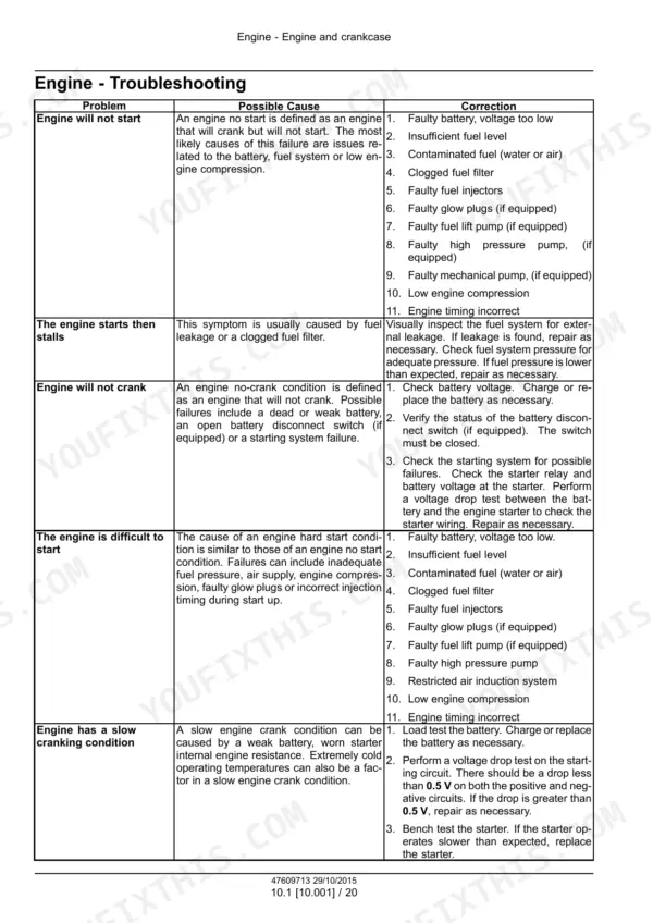
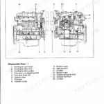
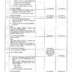
All 415 pages of this Cnh Industrial Cursor® 16 SST Tier 4B (final) and Stage IV Engine Service Manual (OEM #47609713) focus on one thing: getting your Tier 4B/Stage IV powerplant back to factory spec, from bare crankcase to SCR aftertreatment. Inside: a complete engine rebuild sequence spanning cylinder heads, crankshaft and flywheel, connecting rods and pistons, valve drive and gears, turbocharger lines, and Selective Catalytic Reduction system. You also get wiring diagrams, hydraulic schematics, connector pinouts, and a full troubleshooting section that covers the fuel injection system, engine control, electronic modules, and cold start diagnostics. Confirm exhaust temp hits 230°C (446°F) before the SCR system activates, and keep NOx sensor supply above 9V at the ECU and 12V at the sensor heater or you're chasing ghost faults. Emissions faults don't wait. Download now, search by keyword, and pull the exact factory procedure the moment you need it.
What's Inside This Manual
| System | Pages | Key Topics |
|---|
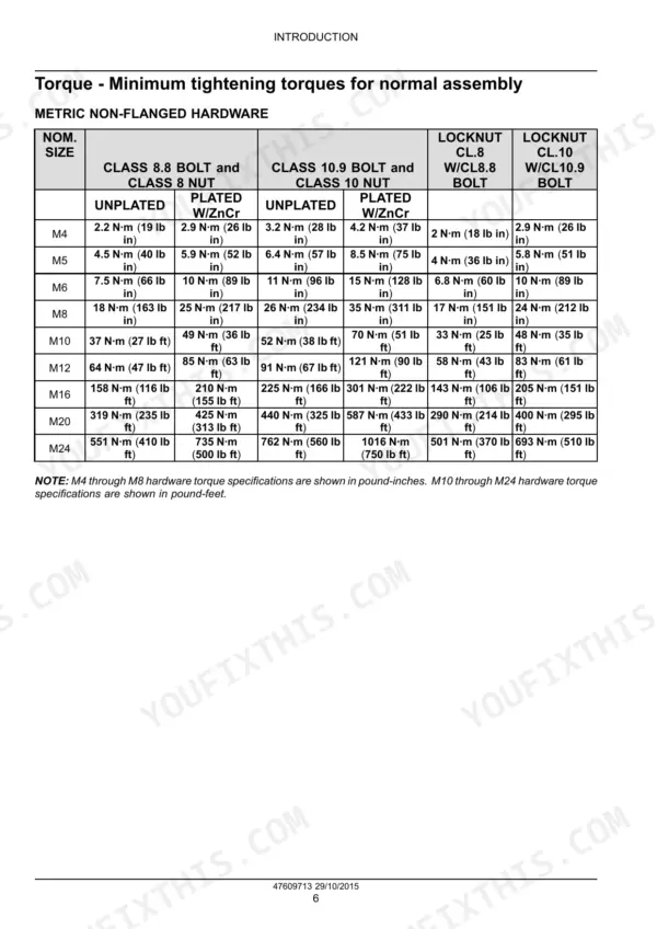
| Introduction | 7-18 | Foreword - Important Notice Regarding Equipment Servicing, Safety Rules, Safety Rules - Ecology and the Environment, Torque - Minimum Tightening Torques for Normal Assembly |
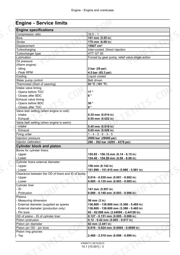
| Engine Mechanical Components | 19-149 | Engine and Crankcase, Cylinder Heads, Pan and Covers, Crankshaft and Flywheel, Connecting Rods and Pistons, Valve Drive and Gears, Balancer and Damper, Pump Drives |
| Engine Fuel and Air Systems | 150-234 | Fuel Filters, Fuel Injection System, Turbocharger and Lines, Intake and Exhaust Manifolds and Muffler, Engine Lubrication System |
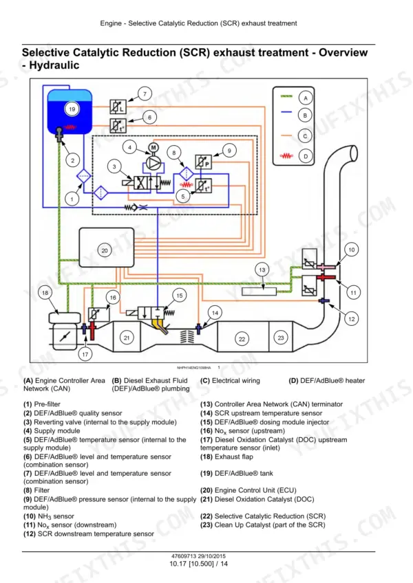
| Engine Cooling and Emissions | 235-314 | Engine Cooling System, Oil Cooler and Lines, Fan and Drive, Selective Catalytic Reduction (SCR) Exhaust Treatment |
| Electrical Systems - 55 | 315-411 | Fuel Injection System, Engine Cooling System, Engine Oil System, Engine Intake and Exhaust System, Engine Control System, Engine Starting System, Cold Start Aid, Electronic Modules |
Quick Reference Specifications
| Specification | Value | Page |
|---|
| ECU data reset procedure for Pressure regulating valve | Connect EST, turn key ON, click 'Configuration' icon (1), select 'Replacement of the Rail Pressure Metering Unit – Reset ECU Data' (1), click 'CONFIGURE SELECTED ITEM' (2), click 'RESET' (1). | p. 181 |
| ECU data reset procedure for Common rail Relief valve | Connect EST, turn key ON, click 'Configuration' icon (1), select 'Replacement of the Rail Pressure Relief Valve (PRV) – Reset ECU Data' (1), click 'CONFIGURE SELECTED ITEM' (2), click 'RESET' (1). | p. 184 |
| NOx sensor minimum supply voltage (ECU) | 9 V | p. 389 |
| NOx sensor minimum supply voltage (Sensor Heater) | 12 V | p. 389 |
| SCR system minimum operating temperature | 230 °C (446 °F) | p. 296 |
| Optimal SCR temperature range | 270.0 - 275.0 °C (518.0 - 527.0 °F) | p. 290 |
| Fuel metering unit resistance value | 2.8 - 3.2 Ω | p. 319 |
| Oil pressure sensor pressure range | 0 - 2400 bar (0 - 34800 psi) | p. 322 |
| Oil pressure sensor supply voltage | 5 V | p. 322 |
| Turbocharger installation torque (Stage 1) | 30 N·m (22 lb ft) | p. 200 |
| Turbocharger installation torque (Stage 2) | 75 N·m (55 lb ft) | p. 200 |
| SCR system optimal operating temperature | higher than 270.0 °C (518.0 °F) | p. 290 |