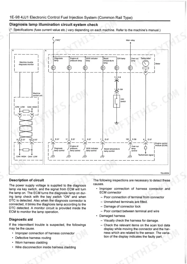
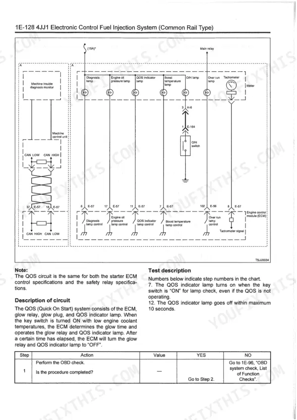


Part of the Isuzu 4JJ1 engine documentation.
This is the Isuzu AI-4JJ1X troubleshooting manual, a 523-page PDF built around diagnosing the electronically controlled 4JJ1X industrial diesel engine. It is a fault-finding manual, centered on diagnostic trouble codes, engine control module wiring, and step-by-step symptom diagnosis rather than teardown.
It opens with the control system overview, how to use the manual, and service precautions, then moves into the fuel injection system, the full procedure of trouble diagnosis, injector inspection, and breaker box use. The core is the Engine Control System chapter and an extensive List of Function Checks covering the OBD system, diagnosis lamp circuits, and scan tool power supply, followed by a detailed List of Trouble Symptom and the special tools needed.
Use it to read and interpret DTCs, trace ECM circuits, and work symptom charts for start failures, smoke, hunting, and control faults on the 4JJ1X.
What's Inside This Manual
| System | Pages | Key Topics |
|---|---|---|
| Control System | 3-4 | Electrical System, Fuel Injection System, Engine Control System, Wiring Diagram of Engine Control Module (Ecm), List of Diagnostic Trouble Codes, List of Trouble Symptom |
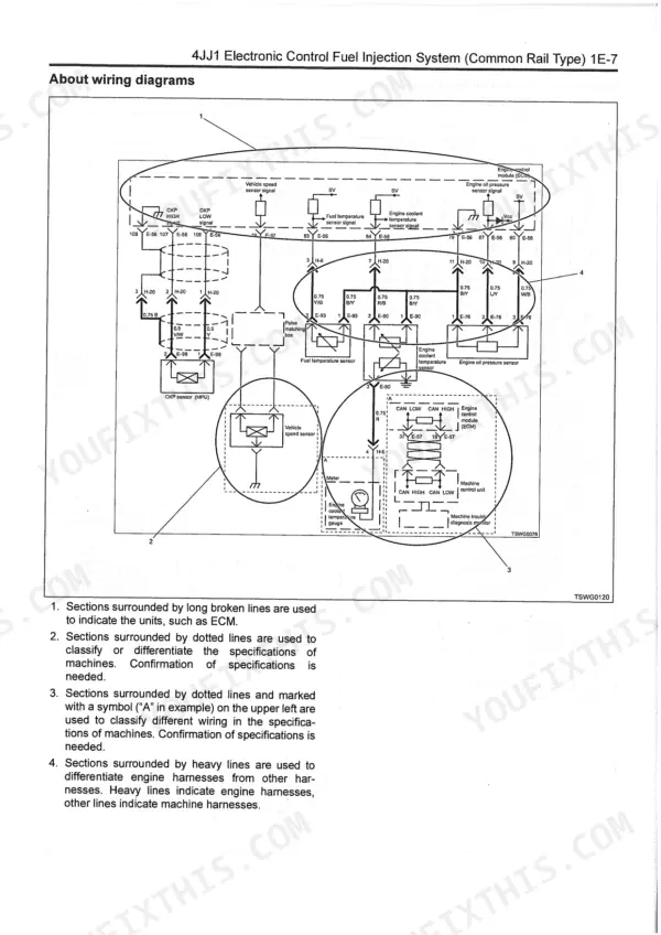
| How to Use This Manual | 5-11 | Table of Abbreviation, Conversion Formula, About Colors of Wirings, About Wiring Diagrams |
| Precautions on Service Work | 12-12 | Electrical System, Commercial Electrical Equipment, Welding Work on the Machine, Damage Caused by Electrostatic Discharge |
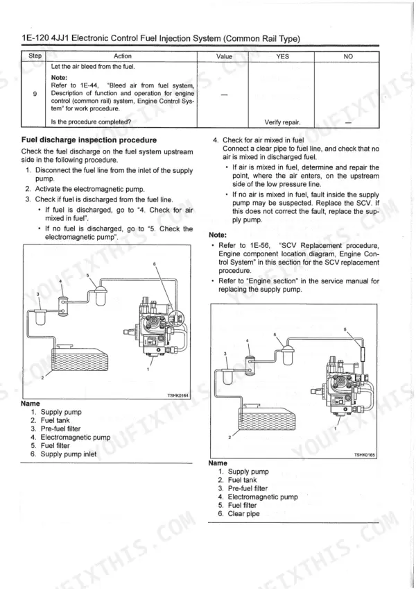
| Fuel Injection System | 13-13 | Fuel Pipe, Injection Amount Control, Injection Pressure Control, System Schematic Diagram, Fuel System, Bleed Air From Fuel System |
| Procedure of Trouble Diagnosis | 14-34 | Trouble Diagnostic Procedure, Interview, Pre-Inspection, How to Read DTC |
| How to Inspect Injector | 35-35 | |
| How to Use Breaker Box | 36-38 | |
| Engine Control System | 39-96 | Engine Control System Function, Fuel Injection Correction, Engine Emergency Stop Function, Input/Output Table |
| List of Function Checks | 97-133 | OBD System Check, Diagnosis Lamp Illumination Circuit System Check, Diagnosis Lamp Blinking Circuit System Check, Scan Tool Power Supply Circuit System Check (Tech2) |
| DTC: P0112 (Flash Code 22) Intake Air Temperature Sensor Fault (Low Voltage Fault, Gnd Short, Short Circuit) | 134-188 | DTC: P0087 (Flash Code 227) Common Rail Low Pressure Fault (No Pressure Feed in Supply Pump), About Recovery From Failure, DTC: P0811 (Flash Code 34) Charge Circuit Fault (Bank 1), DTC: P201 (Flash Code 271) Open Circuit in Injection Nozzle #1 Drive System, DTC: P0118 (Flash Code 23) Engine Coolant Temperature Sensor Input Is High (Open Circuit or Short to Power Supply Circuit), DTC: P0335 (Flash Code 15) Crank Sensor Fault (No Signal), DTC: P1261 (Flash Code 158) Injection Nozzle Common 1 Drive System Fault, DTC: P0815 (Flash Code 19) Starter Cut Relay Fault |
| DTC: P0183 (Flash Code 211) Fuel Temperature Sensor Fault (High Voltage Fault, Open Circuit or Short to Power Supply Circuit) | 189-223 | DTC: P0117 (Flash Code 23) Engine Coolant Temperature Sensor Fault (Low Voltage Fault, Gnd Short, Short Circuit), DTC: P0113 (Flash Code 22) Intake Air Temperature Sensor Fault (High Voltage Fault, Open Circuit or Short to Power Supply Circuit), DTC: P0118 (Flash Code 23) Engine Coolant Temperature Sensor Input Is High (Open Circuit or Short to Power Supply), DTC: P0182 (Flash Code 211) Fuel Temperature Sensor Fault (Low Voltage Fault, Gnd Short) |
| DTC: P0204 (Flash Code 274) Open Circuit in Injection Nozzle #4 Drive System | 224-255 | DTC: P0193 (Flash Code 245) Common Rail Pressure Sensor Fault (High Voltage Fault), DTC: P0192 (Flash Code 245) Common Rail Pressure Sensor Fault (Low Voltage Fault, Short Circuit), DTC: P0202 (Flash Code 272) Open Circuit in Injection Nozzle #2 Drive System, DTC: P0201 (Flash Code 271) Open Circuit in Injection Nozzle #1 Drive System, DTC: P0203 (Flash Code 273) Open Circuit in Injection Nozzle #3 Drive System |
| DTC: P0381 (Flash Code 67) Glow Plug Lamp Circuit Fault | 256-307 | DTC: P0335 (Flash Code 15) Crank Sensor Fault (No Signal), DTC: P0237 (Flash Code 32) Boost Pressure Sensor Fault (Low Voltage Fault, Open Circuit), DTC: P0219 (Flash Code 543) Overrun, DTC: P0238 (Flash Code 32) Boost Pressure Sensor Fault (High Voltage Fault, Short to Power Supply Circuit, Ground Open Circuit), DTC: P0340 (Flash Code 14) Cam Sensor Fault (No Signal) |
| DTC: P0523 (Flash Code 294) Engine Oil Pressure Sensor Fault (High Voltage Fault, Short to Power Supply, Ground Short) | 308-332 | DTC: P0488 (Flash Code 45) EGR Valve Control Fault, DTC: P0487 (Flash Code 44) EGR Position Sensor Fault, DTC: P0522 (Flash Code 294) Engine Oil Pressure Sensor Fault (Low Voltage Fault, Open Circuit, Ground Short), Short to Power Supply |
| DTC: P1261 (Flash Code 158) Injection Nozzle Common 1 Drive System Fault | 333-408 | DTC: P0650 (Flash Code 77) Diagnosis Lamp Circuit Fault, DTC: P0606 (Flash Code 52) Cpu Monitoring Ic Fault, DTC: P0603 (Flash Code 54) Eeprom Fault, DTC: P0601 (Flash Code 53) Rom Fault, DTC: P0606 (Flash Code 51) Cpu Fault, DTC: P0612 (Flash Code 34) Charge Circuit Fault (Bank 2), DTC: P0611 (Flash Code 34) Charge Circuit Fault (Bank 1), DTC: P0615 (Flash Code 19) Starter Cut Relay Circuit Fault |
| DTC: U2106 (Flash Code 85) CAN Timeout Fault | 409-484 | DTC: P1278 (Flash Code 24) Accelerator Sensor 1 Fault (High Voltage Fault), DTC: P1262 (Flash Code 159) Injection Nozzle Common 2 Drive System Fault, DTC: P1271 (Flash Code 24) Accelerator Sensor 1-2 Comparison Fault, DTC: P1277 (Flash Code 24) Accelerator Sensor 1 Fault (Low Voltage Fault), DTC: P1625 (Flash Code 416) Main Relay Fault, DTC: P1283 (Flash Code 24) Accelerator Sensor 2 Fault (High Voltage Fault), DTC: P1282 (Flash Code 24) Accelerator Sensor 2 Fault (Low Voltage Fault), DTC: P1345 (Flash Code 16) Cam Sensor Out of Phase |
| Engine Start Failure | 485-486 | List of Trouble Symptom |
| List of Trouble Symptom | 487-521 | Engine Start Failure, Engine Stall, Engine Hunting, Rough Idling, Engine Output Shortage, Lag Down |
| Special Tool | 522-523 | Digital Multimeter, Tech2 Scan Tool, Terminal Remover, Weather Pack Terminal Remover, Engine Module Programming System |
Quick Reference Specifications
| Specification | Value | Page |
|---|---|---|
| SCV Tightening Torque | 6.9 - 10.8 N·m | p. 59 |
| Overheating Switch Sensor Tightening Torque | 27 - 34 N·m | p. 64 |
| Crankshaft Position Sensor Tightening Torque | 5 N·m | p. 65 |
| Engine Oil Pressure Sensor Tightening Torque | 40 N·m | p. 66 |
| Intake Air Temperature Sensor Tightening Torque | 10.8 - 16.3 N·m | p. 67 |
| Boost Pressure Sensor Tightening Torque | 10 N·m | p. 68 |
| Tacho Sensor Output Voltage | 2.5 V | p. 54 |
| Tacho Sensor Resistance | 2.3±0.2 kΩ | p. 54 |
| System Voltage (at 1000 rpm) | 27.9 - 28.1 V | p. 27 |
| Engine Coolant Temperature (at 1000 rpm) | 73 - 75 °C | p. 27 |
| Barometric Pressure (at 1000 rpm) | 120 kPa | p. 27 |
| Main Fuel Flow (at 1000 rpm) | 9 - 12 mm3/st | p. 27 |