


Part of the Isuzu 6HK1 engine documentation.
This is the Isuzu 6HK1 diesel engine Workshop Manual, an Interim Tier 4 compatible reference running 963 pages. It is delivered as a downloadable PDF you can open on a phone, tablet or computer, or print by section for the workshop.Coverage spans the whole common-rail engine: a service information guide, maintenance information and primary specifications, functional inspection of the starting, fuel, air intake and EGR systems, symptom diagnosis, and a deep set of DTC diagnostics from P0016 through the P2xxx and Uxxxx series. The mechanical section covers the cylinder head, block, crankshaft, and flywheel, and an Electronic Troubleshooting Manual adds the engine wiring diagrams, location diagrams, and connector list.With it you can diagnose DPD regeneration faults, chase injector coil and common-rail pressure codes, sort a boost or VNT problem, and carry out a full mechanical overhaul with Isuzu's own specifications.
What's Inside This Isuzu 6HK1 Manual
| System | Pages | Key Topics |
|---|---|---|
| Service Information Guide | 6-25 | Contents Included in Service Information, Plastic Gauge, Recommended Liquid Gasket, Thread Locking Adhesive Agent |
| Maintenance Information | 26-94 | Primary Specifications, Function, Structure, and Operation, Maintenance Precautions, Introduction to Trouble Diagnosis |
| Functional Inspection | 95-112 | Starting System Check, Fuel System Check, Air Intake and Exhaust System Check, EGR and Glow Control System Check |
| Symptom Diagnosis | 113-128 | DPD System Regeneration Issues, Engine Start Failure and Stalling, Engine Hunching or Rough Idling, Excessive Exhaust Smoke |
| DTC Information | 129-228 | Dtc P0016 - P0093, DTC Descriptions, DTC Mapping Table |
| Engine Control | 229-764 | Table of Contents, DTC Diagnostics, DTC P0016 - Crankshaft/Camshaft Correlation, DTC P0045 - Turbocharger Boost Control, DTC P0087 - Fuel Rail Pressure Too Low, DTC Diagnostics: P01xx - P04xx Series, DTC Diagnostics: P05xx - P1xxx Series, DTC Diagnostics: P2xxx - Uxxxx Series |
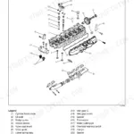
| Mechanical | 277-828 | Idle Gear, Flywheel and Housing, Oil Pan, Crankshaft Seals, Cylinder Head Cover, Cylinder Head Assembly, Cylinder Block, DTC Mapping Table |
| DTC Information (Continued) | 415-504 | Mass Air Flow Circuit (P0102, P0103), Temperature Sensor Circuits (P0112 - P0118), Fuel Temperature and Pressure Sensor Circuits, Injector Circuits (P0201 - P0206) |
| Electronic Troubleshooting Manual (ETM) | 829-963 | Using the Wiring Diagram, Engine Wiring Diagrams, Location Diagram, Connector List |
Quick Reference Specifications
| Specification | Value | Page |
|---|---|---|
| Boost pressure (DTC P0234 setting condition) | 300 kPa {3 kgf/cm2 / 44 psi} or higher for 5 seconds or longer | p. 159 |
| Actual common rail pressure (DTC P0093 setting condition) | 15 MPa {153 kgf/cm2 / 2175 psi} or lower for 3 seconds or longer | p. 138 |
| Injector harness intermediate connector resistance | 2.0 Ω | p. 120 |
| Compression Pressure (Specified Value) | 3240.0 kPa | p. 109 |
| Compression Pressure (Limit) | 2260.0 kPa | p. 109 |
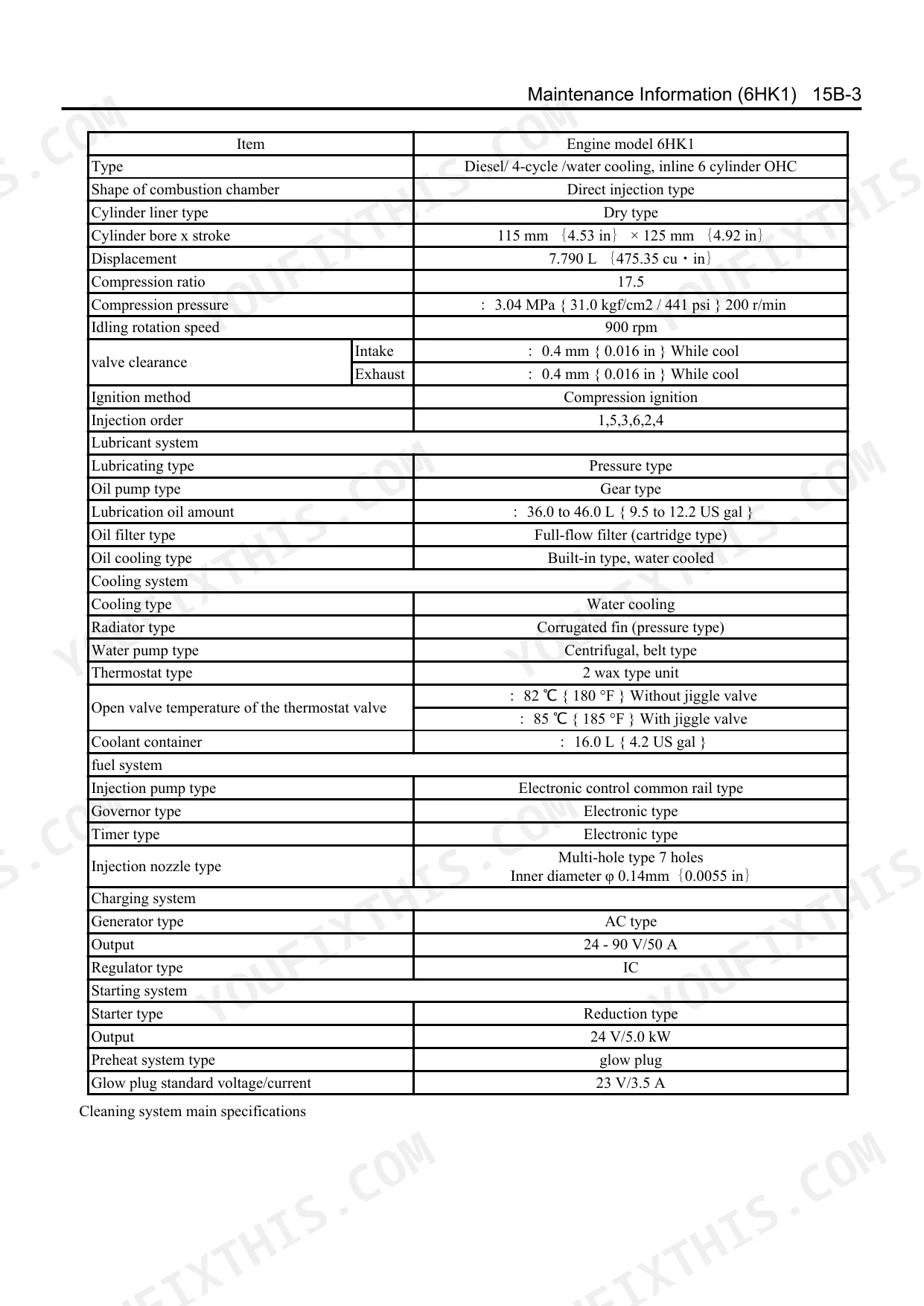
| Valve Clearance (Intake & Exhaust, Cold) | 0.4 mm | p. 28 |
| Cylinder Bore | 115 mm | p. 28 |
| Lubrication Oil Amount | 36.0 to 46.0 L | p. 28 |
| Thermostat Opening Temperature (without jiggle valve) | 82 °C | p. 28 |
| Glow Plug Standard Current | 3.5 A | p. 28 |
| Cylinder Head Cover Bolt Torque | 13 N·m | p. 77 |
| M14 Cylinder Head Bolt Torque (Step 1) | 98 N·m | p. 113 |
Isuzu 6HK1 Common Problems This Manual Covers
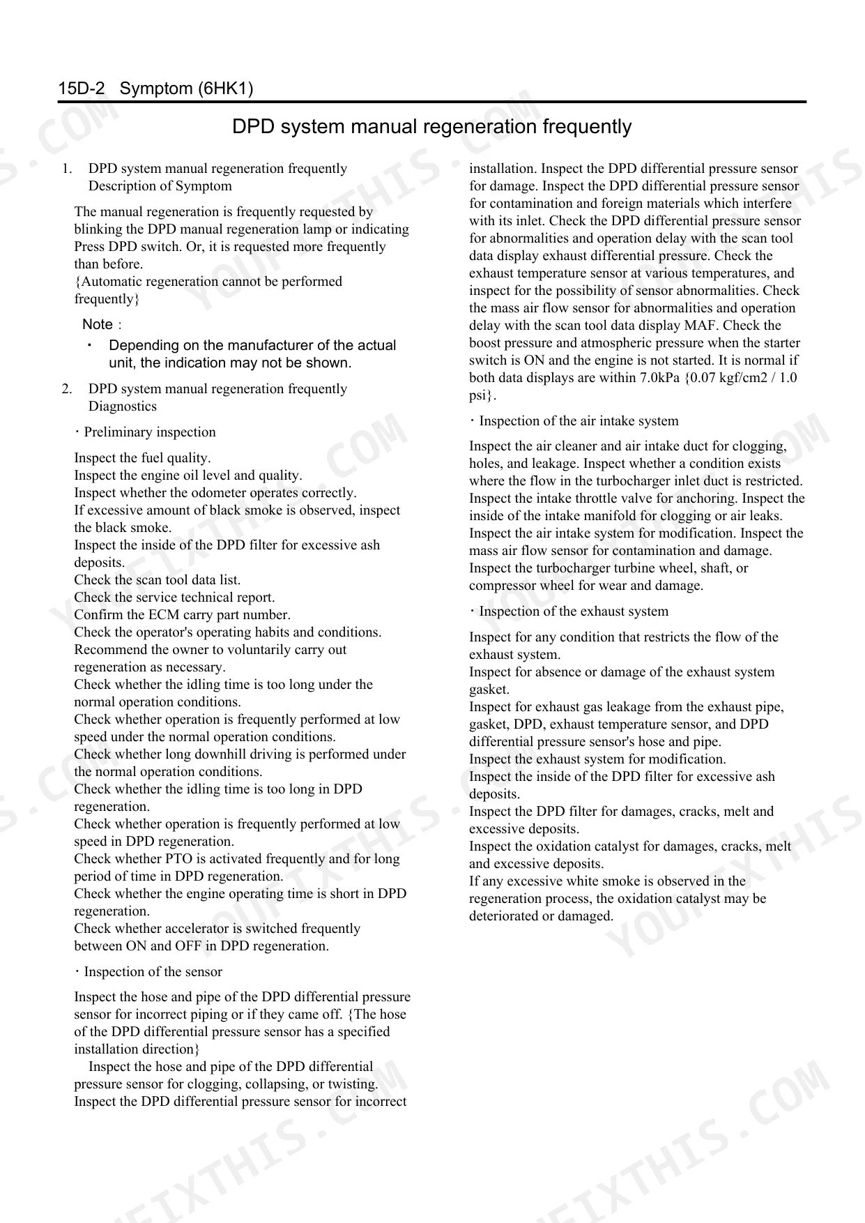
DPD regeneration problems and excessive smoke
Failed or incomplete DPD regeneration shows up as heavy exhaust smoke and reduced performance. The Symptom Diagnosis section walks through regeneration issues alongside stalling and rough idle symptoms.
Manual Section: Symptom Diagnosis p. 113Injector coil open-circuit faults
The 6HK1 injectors are prone to coil failures that set open-circuit codes such as P0204 to P0206 and cause rough running. The DTC Information section provides the descriptions, mapping table, and diagnostics.
Manual Section: DTC Information p. 129Common-rail pressure faults and hard starting
Low or abnormal rail pressure, including a P0093 condition of 15 MPa or lower, can leave the engine hard to start or unable to run. The DTC Information section covers the rail pressure and suction control valve diagnostics.
Manual Section: DTC Information p. 129Turbocharger boost or VNT control faults
Boost pressure codes such as P0234 and P0299, and VNT current faults, cause power loss and limp behaviour. The Engine Control section holds the DTC diagnostics for turbocharger boost control.
Manual Section: Engine Control p. 229Oil leaks from seals or cylinder head
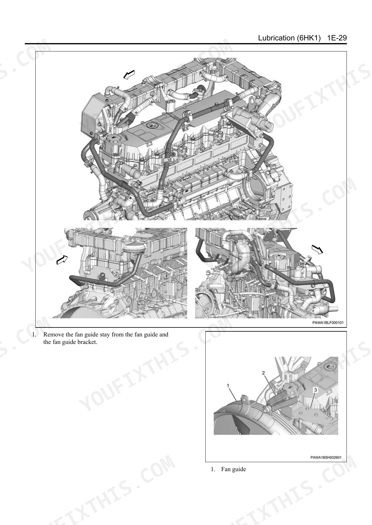
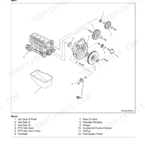
Leaks around the crankshaft seals, oil pan, or cylinder head cover are common as the engine ages. The Mechanical section details the idle gear, flywheel and housing, crankshaft seals, and cylinder head assembly.
Manual Section: Mechanical p. 277Starting, fuel, or air intake check failures
No-start and low-power complaints often come back to the starting, fuel, air intake and exhaust, or EGR and glow systems. The Functional Inspection section gives the check procedures for each of these systems.
Manual Section: Functional Inspection p. 95Frequently Asked Questions
Which engine does this manual cover?
It is the workshop manual for the Isuzu 6HK1 Interim Tier 4 compatible diesel engine, a single 963-page document covering that common-rail engine.
Does it include DTC diagnostic codes?
Yes. The DTC Information section (page 129) documents diagnostic trouble codes from P0016 through P0093 and beyond, with descriptions, setting conditions, and a DTC mapping table. p. 129
Does it include wiring diagrams?
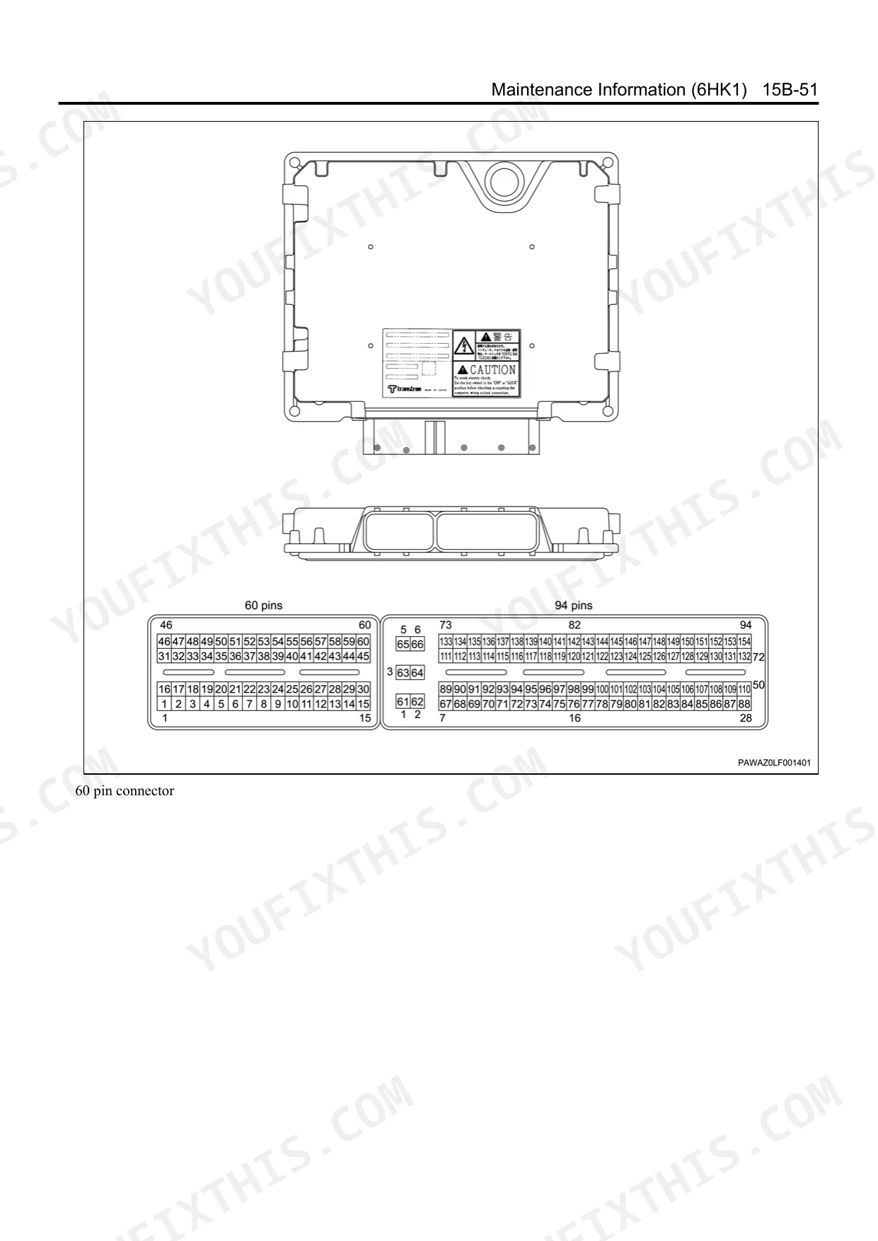
Yes. The Electronic Troubleshooting Manual section (page 829) provides the engine wiring diagrams, guidance on using them, location diagrams, and the connector list. p. 829
Does it cover engine mechanical overhaul?
Yes. The Mechanical section (page 277) covers the cylinder head cover and assembly, cylinder block, crankshaft seals, oil pan, flywheel and housing, and idle gear for a full overhaul. p. 277
How quickly can I access this Isuzu 6HK1 manual after buying?
You get a 963-page searchable PDF that downloads instantly after checkout. Open it on your laptop, tablet, or phone and bring it right to the shop floor.
Can I print this Isuzu 6HK1 manual?
Yes. The PDF has no DRM restrictions, so print any page or section you need for your shop. Works with any standard printer.
Are there wiring harness diagrams in this Isuzu 6HK1 manual?
Included. This manual covers complete wiring harness diagrams, electrical circuits, and connector pinouts starting on page 829.


Reviews
There are no reviews yet.