


Covering all four variants (AA-4BG1T, AA-6BG1, BB-4BG1T, BB-6BG1T), this 220-page workshop manual (OEM #IDE-2370) is built around getting your industrial diesel torn down and reassembled to factory spec. Thirty pages of exploded views and 100 pages of step-by-step procedures walk you through complete disassembly, inspection, and reassembly. Another 25 pages list torque specs; connecting rod bolts, for example, call for 39 N·m first, then 60 to 90 degrees of rotation. Twenty-two pages of troubleshooting cover hard starting, unstable idle, insufficient power, and excessive fuel consumption. Wiring diagrams detail starter and alternator circuits, and injection pump calibration data is included for all four engine variants. Valve clearance is set at 0.40 mm cold. The bookmarked PDF is searchable and opens on any device.
What's Inside This Isuzu AA-4BG1T, AA-6BG1, BB-4BG1T, BB-6BG1T Manual
| System | Pages | Key Topics |
|---|---|---|
| Maintenance | 28-47 | Lubricating System, Fuel System, Cooling System, Injection Timing |
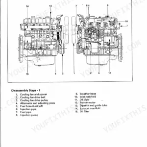
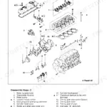
| Engine Assembly I (Disassembly) | 48-63 | External Parts Disassembly Steps, Major Components, Rocker Arm And Shaft Disassembly, Cylinder Head Disassembly |
| Engine Assembly II (Inspection & Repair) | 64-93 | Cylinder Head, Valve Guide, Valve Spring, Tappet |
| Engine Assembly III (Reassembly) | 94-123 | Piston and Connecting Rod Reassembly, Cylinder Head Reassembly Steps, Rocker Arm and Rocker Arm Shaft Reassembly, Major Component Reassembly Steps I |
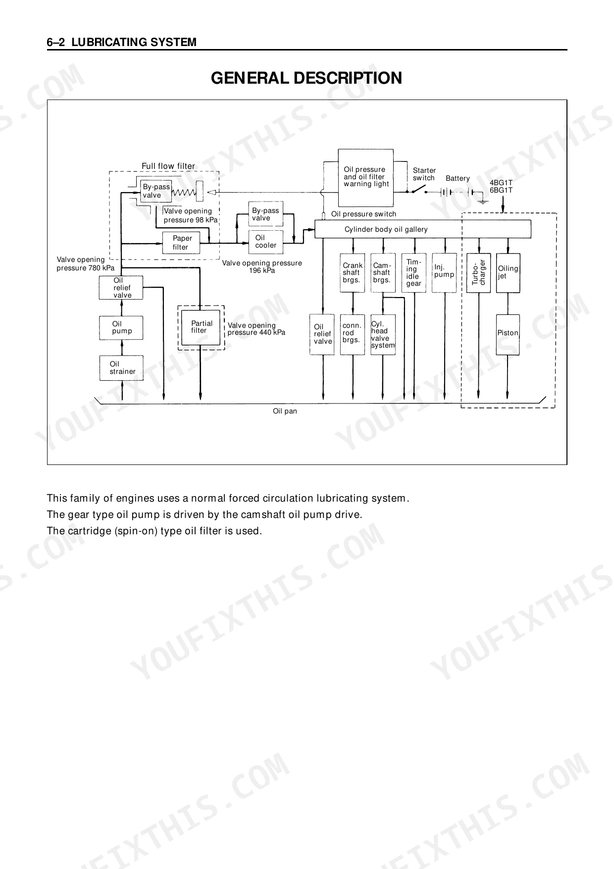
| Lubricating System | 124-129 | - |
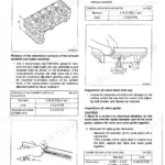
| Cooling System | 130-133 | General Description, Thermostat |
| Fuel System | 134-143 | General Description, Injection Nozzle, Injection Pump Calibration Data |
| Turbocharger | 144-147 | General Description, Turbocharger Identification, Inspection And Repair |
| Air Compressor | 148-155 | General Description, Disassembly Steps, Inspection And Repair, Reassembly Steps |
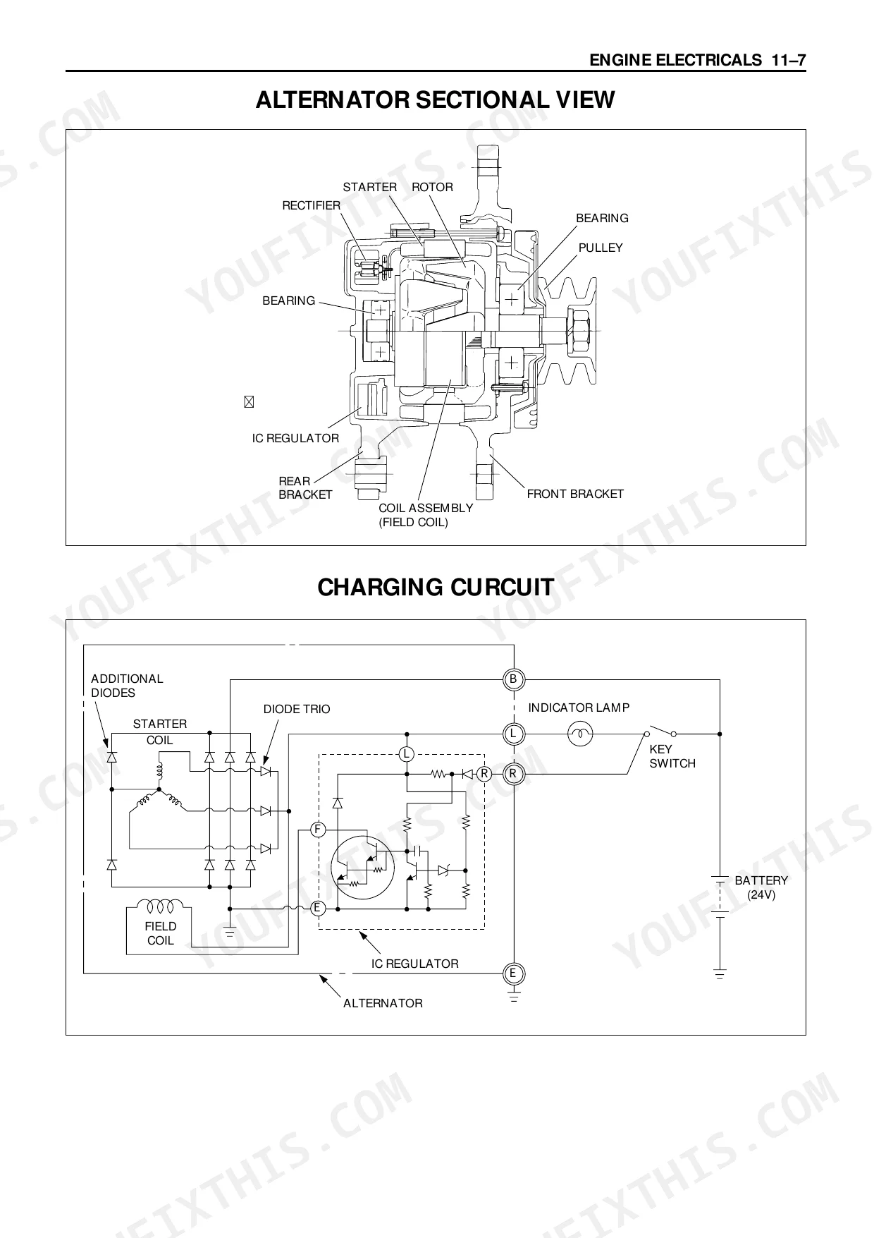
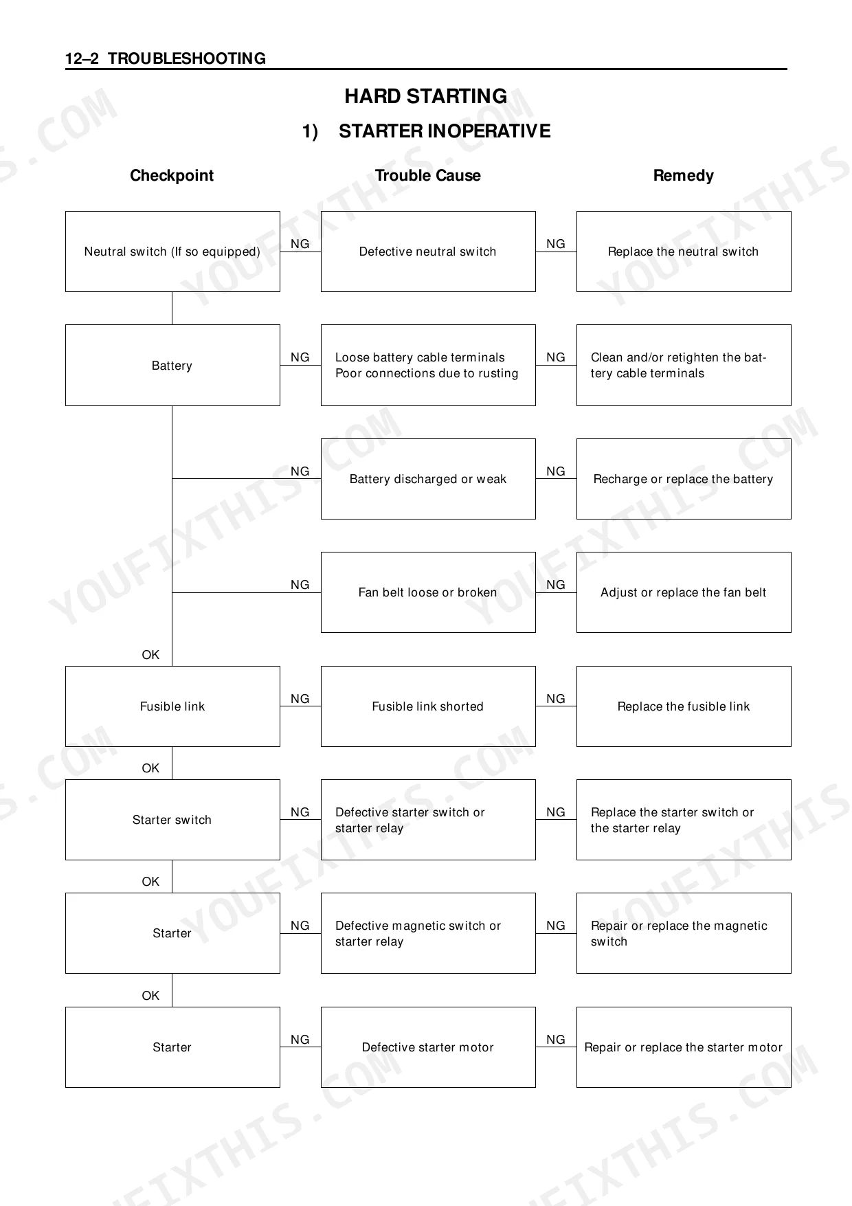
| Engine Electricals | 156-163 | Starter Identification, Starter Main Data And Specifications, Starter Motor Sectional View, Alternator Identification |
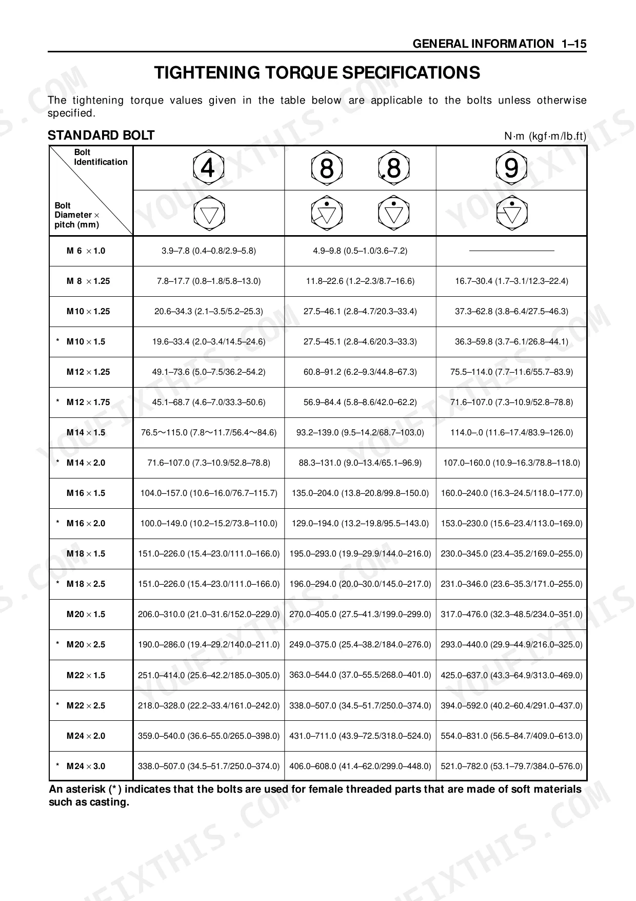
| Troubleshooting | 164-187 | Hard Starting, Unstable Low Idling, Insufficient Power, Excessive Fuel Consumption |
| Special Tool List | 188-191 | - |
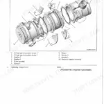
| Repair Standards | 192-211 | General Rules, Engine Body, Main Operating Parts, Valve System |
| Conversion Table | 212-220 | - |
Quick Reference Specifications
| Specification | Value | Page |
|---|---|---|
| All Models | ||
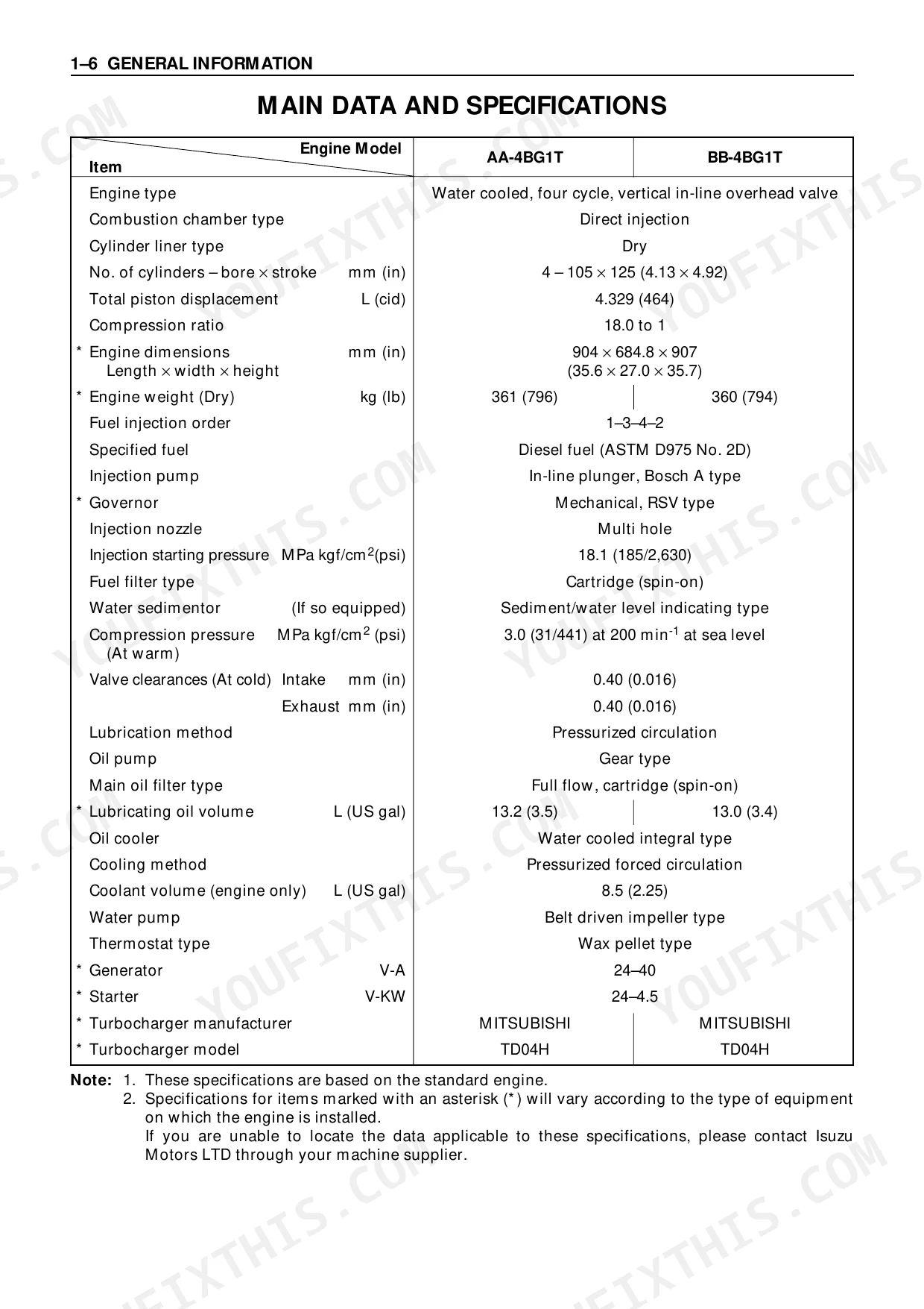
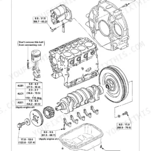
| Crankshaft Bearing Cap Bolt Torque | 226-245 (23.0-25.0/166-181) N·m (kgf·m/lb.ft) | p. 104 |
| Connecting Rod Bolt Torque and Angle | 1st step 39 (4/29) N·m (kgf·m/lb.ft), 2nd step 60°–90° | p. 105 |
| Valve Clearance (At cold) | 0.40 mm | p. 7 |
| Compression Pressure (At warm) | 3.0 MPa | p. 7 |
| Injection Starting Pressure | 18.1 MPa | p. 7 |
| Compression Pressure Limit | 2.5 MPa | p. 42 |
| Thermostat Valve Opening Temperature | 80-84 °C | p. 34 |
| Rocker Arm Screw Lock Nut Torque | 21-30 N·m | p. 36 |
| BB-6BG1T | ||
| Lubricating Oil Volume | 21.5 L | p. 8 |
| AA-6BG1, BB-6BG1T | ||
| Coolant Volume (engine only) | 12 L | p. 8 |
| Flywheel Bolt Torque | 197-240 N·m | p. 108 |
| Crankshaft Pulley Nut Torque | 539-637 N·m | p. 109 |
Isuzu AA-4BG1T, AA-6BG1, BB-4BG1T, BB-6BG1T Common Problems This Manual Covers
Isuzu 4BG1T/6BG1 engine turns over but will not start, no fuel reaching injectors p. 165
Follow the hard starting troubleshooting procedures on page 165. Bleed the fuel system starting at the injection pump inlet, then work toward the injectors. Inspect the fuel filter for water contamination and replace if needed. Verify injection nozzle opening pressure is at 18.1 MPa using a nozzle tester; weak nozzles will not atomize properly and the engine won't fire. Clean or replace the fuel lift pump if delivery volume is low.
Manual Section: TroubleshootingLow oil pressure warning at idle, gauge reads near zero when engine is warm p. 124
Inspect the oil strainer screen and oil pump pickup for blockage or debris. Verify you are running the correct viscosity oil for ambient temperature. Remove and test the relief valve on page 124 for sticking or a broken spring. Measure bearing clearances against repair standards on page 192; worn main or rod bearings will bleed off pressure at idle. Replace the oil pressure sender to rule out a faulty gauge before tearing into the engine.
Manual Section: Lubricating SystemEngine overheating under load, coolant temperature climbing past normal range p. 130
Verify the thermostat valve opening temperature; it should open between 80 and 84 °C per page 34. Remove and test the thermostat in a hot water bath if you suspect it is stuck closed. Inspect the fan belt for proper tension and the radiator core for external blockage. Confirm the water pump impeller is not corroded or spinning on the shaft. Retarded injection timing generates excess heat, so check timing if other causes are ruled out.
Manual Section: Cooling SystemRough idle and unstable RPM at low speed, engine hunts or surges p. 169
Adjust valve clearance to 0.40 mm cold on all cylinders per page 36, torquing rocker arm lock nuts to 21 to 30 N·m. Check the governor linkage for binding or worn bushings. Inspect the fuel system for air leaks at all line connections between the tank and injection pump. Verify idle speed adjustment on the injection pump. If hunting continues, the pump may have worn internal components; refer to calibration data on page 134.
Manual Section: TroubleshootingDark black exhaust smoke under load, noticeable power loss on turbo models p. 144
Pull the air cleaner element first; a clogged filter starves the engine and causes rich running. Examine the turbocharger compressor wheel on page 144 for oil buildup or contact marks on the housing. Measure compression pressure warm; any cylinder below 2.5 MPa (page 42) indicates rings, liner, or valve problems dragging performance down. Verify injection nozzle spray pattern and replace any nozzle that dribbles or streams instead of atomizing.
Manual Section: TurbochargerKnocking or slapping noise from lower engine block, louder at idle p. 184
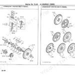
Measure connecting rod bearing clearances against repair standards on page 192. Torque connecting rod bolts in two steps: first to 39 N·m, then rotate 60 to 90 degrees per page 105. Inspect piston pin fit and piston skirt for scoring or excessive wear. Listen with a stethoscope to isolate which cylinder is knocking before disassembly. If the knock disappears under load, suspect rod bearing wear; if it worsens, suspect piston slap from worn liners.
Manual Section: TroubleshootingFrequently Asked Questions
What are the torque specifications for AA-6BG1 cylinder head bolts?
For a laminated steel gasket, AA-6BG1 cylinder head bolts use a 3-step angular method. First step: 69 N·m (51 lb.ft). Second step: 88 N·m (65 lb.ft). Final step: rotate an additional 90° to 120°. Apply molybdenum disulfide grease to the threads and setting faces before tightening.
What are the torque specifications for BB-4BG1T main bearings?
Torque the BB-4BG1T main bearing cap bolts to 226-245 N·m (166-181 lb.ft). Lubricate the bolts with engine oil before installation. Tighten a little at a time in the numerical order shown in the manual's illustration.
How will I receive this Isuzu AA-4BG1T, AA-6BG1 Workshop Manual?
Instant PDF download. The full 220-page searchable Workshop Manual is available immediately after payment. Open it on your laptop, tablet, or phone right in the shop.
Am I able to print pages from this Isuzu AA-4BG1T, AA-6BG1 manual?
Yes, print as many copies as you need. There are no restrictions. Many mechanics print the section they need and bring it to the shop floor.
Are there wiring harness diagrams in this Isuzu AA-4BG1T, AA-6BG1 manual?
Yes. This manual includes complete electrical wiring diagrams, wire routing, and connector pinouts.
Document Quality
This is a scanned copy of the original workshop manual, but you can search the full text and copy content thanks to a good quality OCR layer. The text is clear and easy to read, while the diagrams and illustrations are scanned line art; they are detailed and most labels are legible, though they will pixelate when zoomed in very closely. The pages are clean and free of any marks or stains, but you will find several blank "MEMO" pages intended for notes throughout the document.
Reviews
There are no reviews yet.