This is the Isuzu A-4JG1 industrial diesel engine Workshop Manual, applicable to 1999 and later models and running 223 pages. It is delivered as a downloadable PDF you can open on a phone, tablet or computer, or print for the workshop.
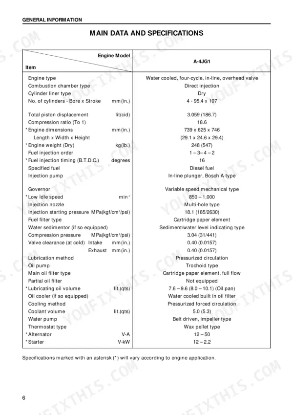
The manual carries a complete overhaul from front to back: maintenance and identification, engine disassembly, inspection and repair, and reassembly, followed by the lubricating, cooling, and fuel systems, engine electricals, troubleshooting, a special tool list, repair standards, and conversion tables. The A-4JG1 is a 3.059 L four-cylinder diesel with an 18.6 to 1 compression ratio.
With it you can chase hard starting, cure rough idle, sort overheating or fuel-related power loss, set valve clearances and injection timing, and rebuild the engine to Isuzu's published repair standards and torque values.
What's Inside This Manual
| System | Pages | Key Topics |
|---|---|---|
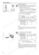
| Maintenance | 19-30 | Model and Injection Pump Identification, Fuel System, Cooling System, Valve Clearance Adjustment |
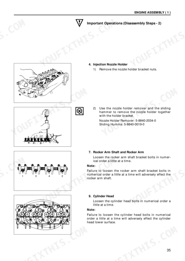
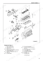
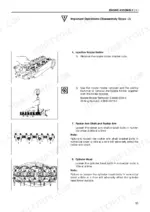
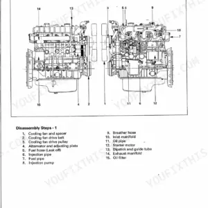
| Engine Assembly (Disassembly) | 31-48 | General Description, Main Component Disassembly, Cylinder Head and Timing Gear Disassembly, Internal Component Disassembly |
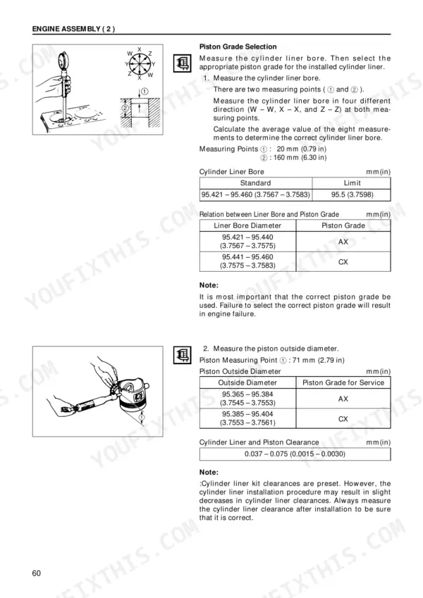
| Engine Assembly (Inspection and Repair) | 49-82 | Cylinder Head, Valve Guide, Valve and Valve Seat Insert, Valve Spring |
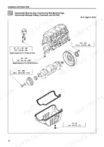
| Engine Assembly (Reassembly) | 83-110 | Rocker Arm Shaft and Rocker Arm, Cylinder Head, Piston and Connecting Rod, Camshaft and Timing Gear |
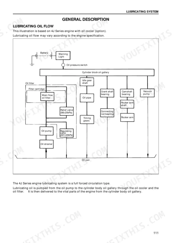
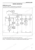
| Lubricating System | 111-122 | Main Data and Specifications, General Description, Oil Pump, Oil Pump Disassembly |
| Cooling System | 123-128 | Main Data and Specifications, General Description, Thermostat |
| Fuel System | 129-142 | Main Data and Specifications, General Description, Injection Nozzle, Fuel Filter and Water Separator |
| Engine Electricals | 143-170 | Starter, Alternator |
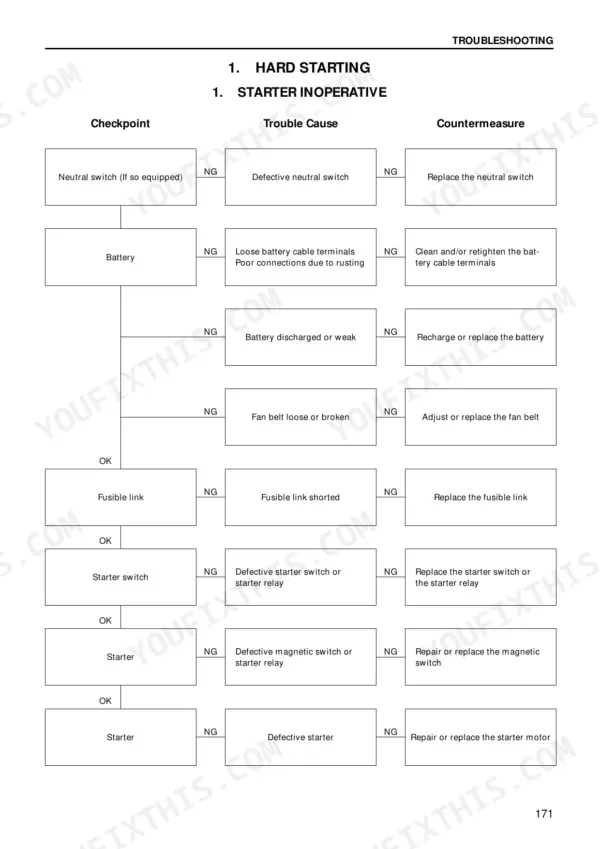
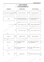
| Troubleshooting | 171-196 | Hard Starting, Unstable Idling, Insufficient Power, Excessive Fuel Consumption |
| Special Tool List | 197-200 | |
| Repair Standards | 201-214 | General Rules, Engine Body, Main Operating Parts, Valve System |
| Conversion Table | 215-223 |
Quick Reference Specifications
| Specification | Value | Page |
|---|---|---|
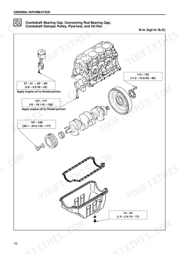
| Crankshaft Bearing Cap Torque | 157 – 177 N·m (16 – 18 kgf·m / 116 – 130 lb.ft) | p. 97 |
| Thermostat Initial Opening Temperature | 82 °C (180 °F) | p. 24 |
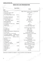
| Compression Pressure (Standard) | 3.04 MPa (31 kgf/cm² / 441 psi) at 200 rpm | p. 8 |
| Water Separator Drain Plug Torque | 9 – 15 N·m (0.9 – 1.5 kgf·m / 7 – 11 lb.ft) | p. 22 |
| Injection Timing (static, B.T.D.C.) | 16° B.T.D.C. | p. 8 |
| Engine Displacement | 3.059 L (186.7 cid) | p. 8 |
| Compression Ratio | 18.6 To 1 | p. 8 |
| Fuel Injection Order | 1 – 3– 4 – 2 | p. 8 |
| Valve Clearance (Cold) | 0.40 mm (0.0157 in) | p. 8 |
| Cylinder Head Bolt Torque (1st Step) | 44 – 54 N·m (4.5 – 5.5 kgf·m / 33 – 39 lb.ft) | p. 11 |
| Connecting Rod Bearing Cap Torque | 27 – 31 N·m (2.8 – 3.2 kgf·m / 20 – 23 lb.ft) → then 45° – 60° | p. 12 |
| Injection Nozzle Opening Pressure | 18.1 MPa (185 kgf/cm² / 2,630 psi) | p. 8 |