


This JCB Service Manual covers the 500 Series telehandlers built from machine serial number 561001, including the 525-58, 525-67, 527-58, 527-67, 530-67, 535-67, 530-95, 530-110, 530-120, 537-120, and 537-130, together with their Farm Special, Farm Special Plus, Basic Servo, PlaceAce, and Servo option variants. Publication number 9803/3600, it runs to 736 pages.The machines use the Perkins 1000 Series four cylinder engine. The manual walks through the hydraulics, boom shimming, the PlaceAce and Servo control systems, the Syncro Shuttle and Powershift transmissions, axles, brakes, hydraulic steering, and the electrical system, with technical data tables for each model.Use it to set relief valve pressures, torque the wheel nuts, overhaul the hydraulic pump, and trace wiring faults on your Loadall.
What's Inside This JCB 525–537 Manual
| System | Pages | Key Topics |
|---|---|---|
| General | 3-33 | Fluids, Lubricants |
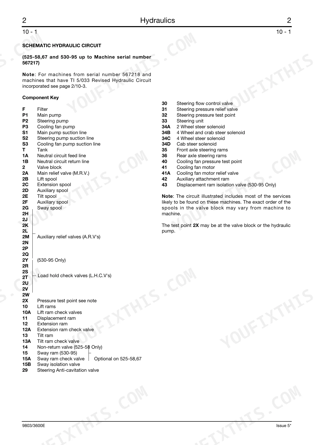
| Hydraulics | 34-175 | Technical Data (525-58/67, 527-58/67, 530-67 & 535-67, 530-120, 530-110, 530-95, 537-120, 537-130) |
| Body and Framework | 176-225 | Boom Shimming - Typical Method, Boom Shimming - 525-58/67, 527-58/67, 530-67, 535-67, Boom Shimming - 530-95, Boom Shimming - 530-110, Boom Wear Pads Shimming - 530-120 |
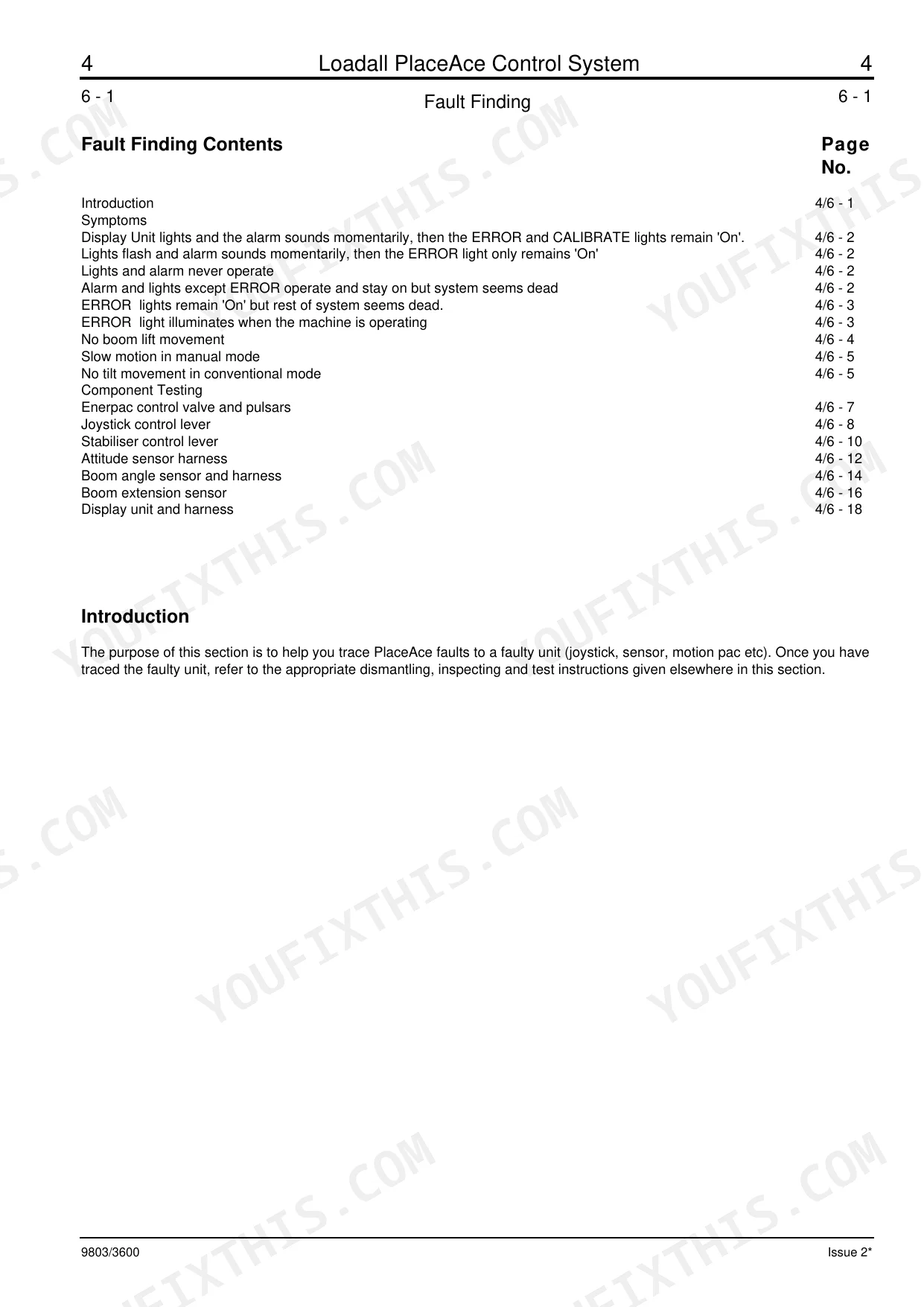
| PlaceAce Control System | 226-293 | Technical Data (530-110, 530-120), Control System Description, Valve Block Operation, Pulsar Description & Operation, Valve Block Removal & Replacement |
| Servo and Basic Servo Control System | 294-356 | Technical Data (525-58/67, 527-58/67, 530-67 & 535-67, 530-110/120), Servo Control System Description (530-110/120) |
| Engine | 357-382 | Technical Data, Engine Cover, Engine Oil Filter, Fuel Filter, Fuel Pump, Bleeding, Cooling System, Alternator Drive Belt |
| Transmission | 383-520 | Syncro Shuttle Technical Data, Syncro Shuttle General Description, Powershift Technical Data, Recovery Procedure, Checking & Changing Oil |
| Axles | 521-578 | Technical Data (525-58/67, 527-58/67, 530-67/95 & 535-67, 530-120, 537-120/130, 530-110), Road Wheel Removal & Replacement, Front Axle Breather Removal & Replacement |
| Brakes | 579-610 | Technical Data (525-58/67, 527-58/67, 530-67 & 535-67, 530-120, 537-120/130, 530-95/110), Parking Brake Adjusting & Testing, Parking Brake Dismantling & Assembly |
| Hydraulic Steering | 611-664 | Technical Data, Flow Regulating Valve Operation, Tandem Steering/Fan Pump Dismantling & Assembly, Steering/Fan Pump Removal & Replacement |
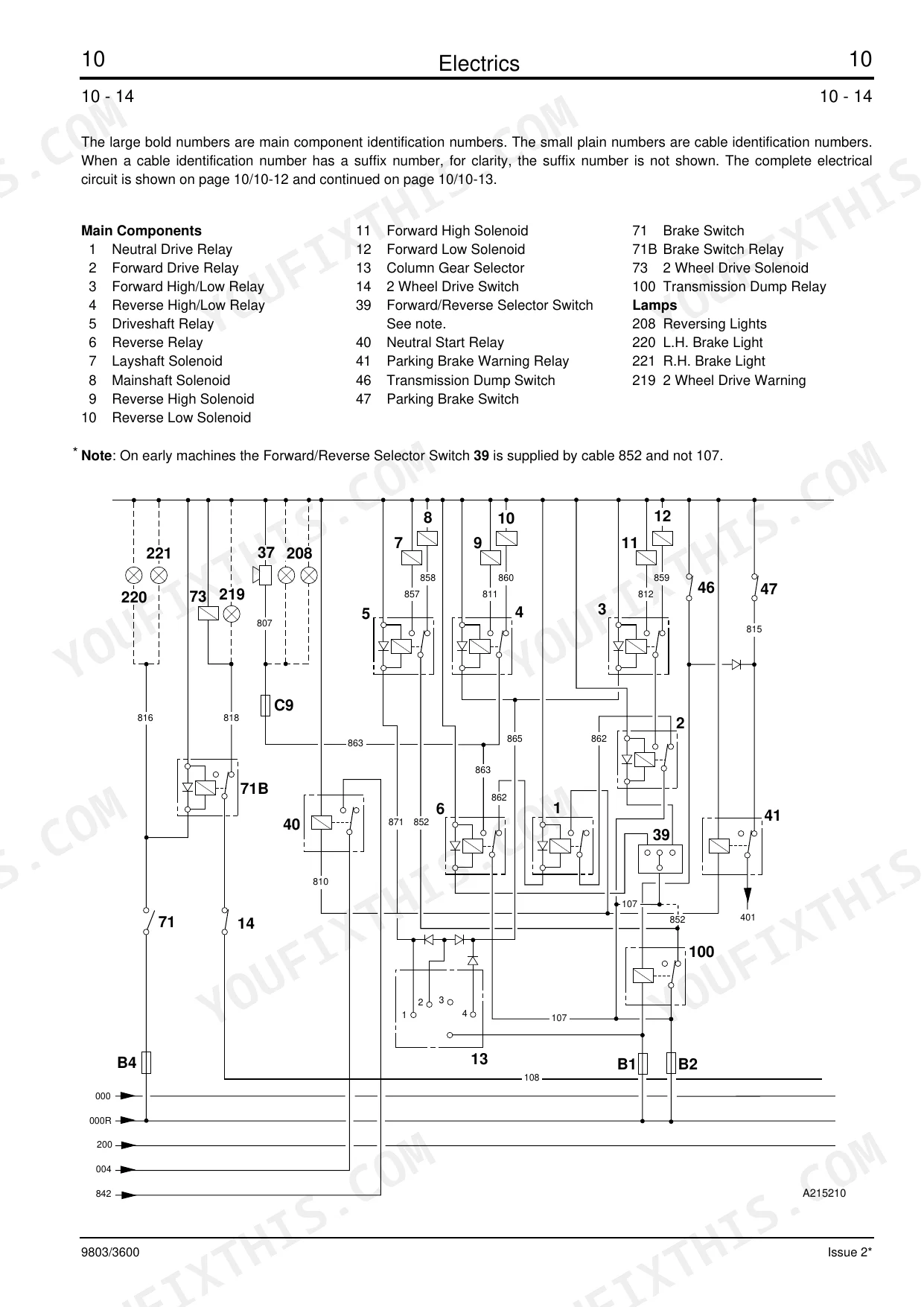
| Electrics | 665-720 | Introduction, Technical Data, Fuses, Relay Location, Test Methods, Batteries Testing, Alternator (Precautions, Testing, Removal & Replacement, Dismantling & Assembly) |
Quick Reference Specifications
| Specification | Value | Page |
|---|---|---|
| All Models | ||
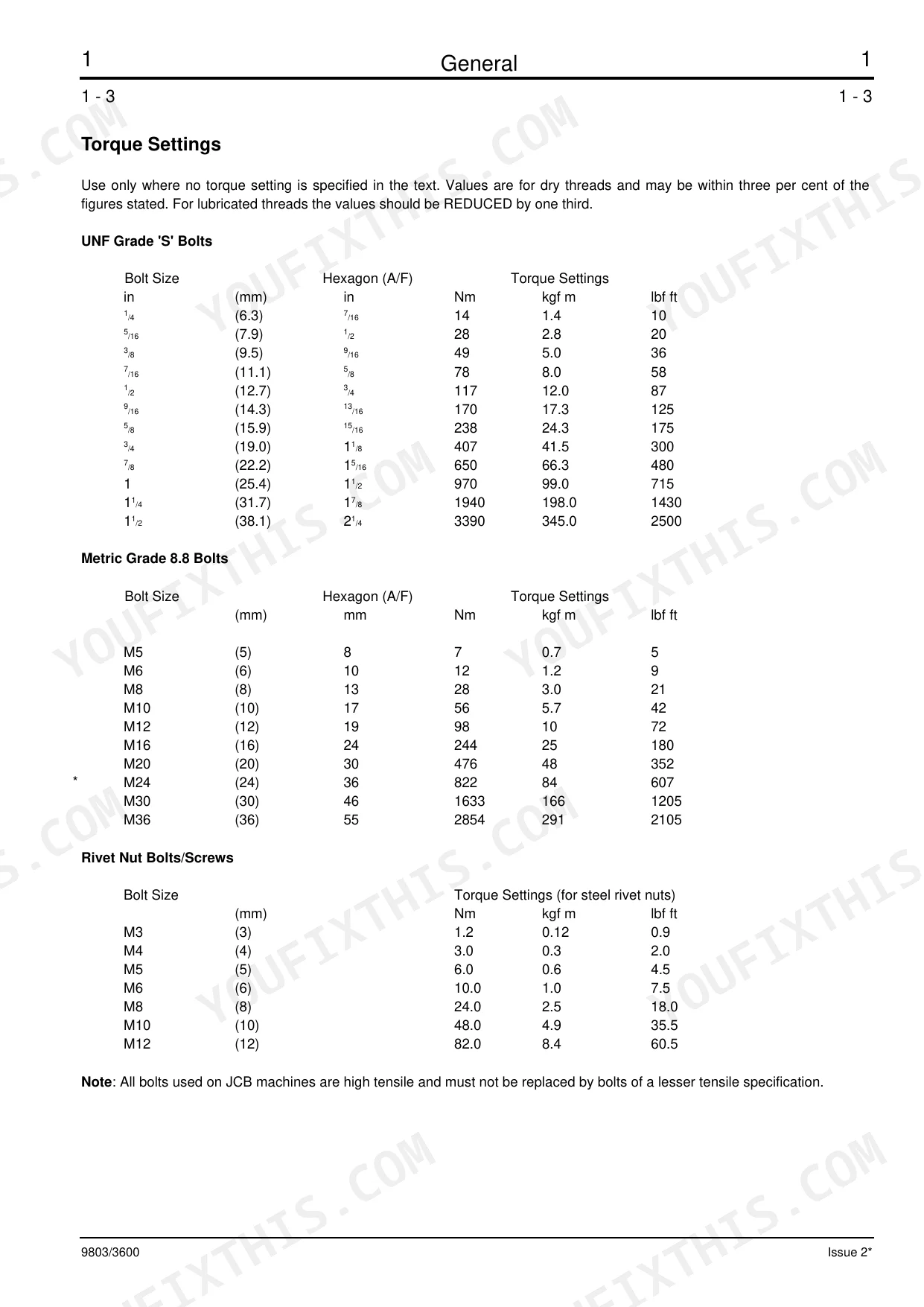
| Roadwheel retaining nuts torque | 680 Nm (69 kgf m, 500 lbf ft) | p. 527 |
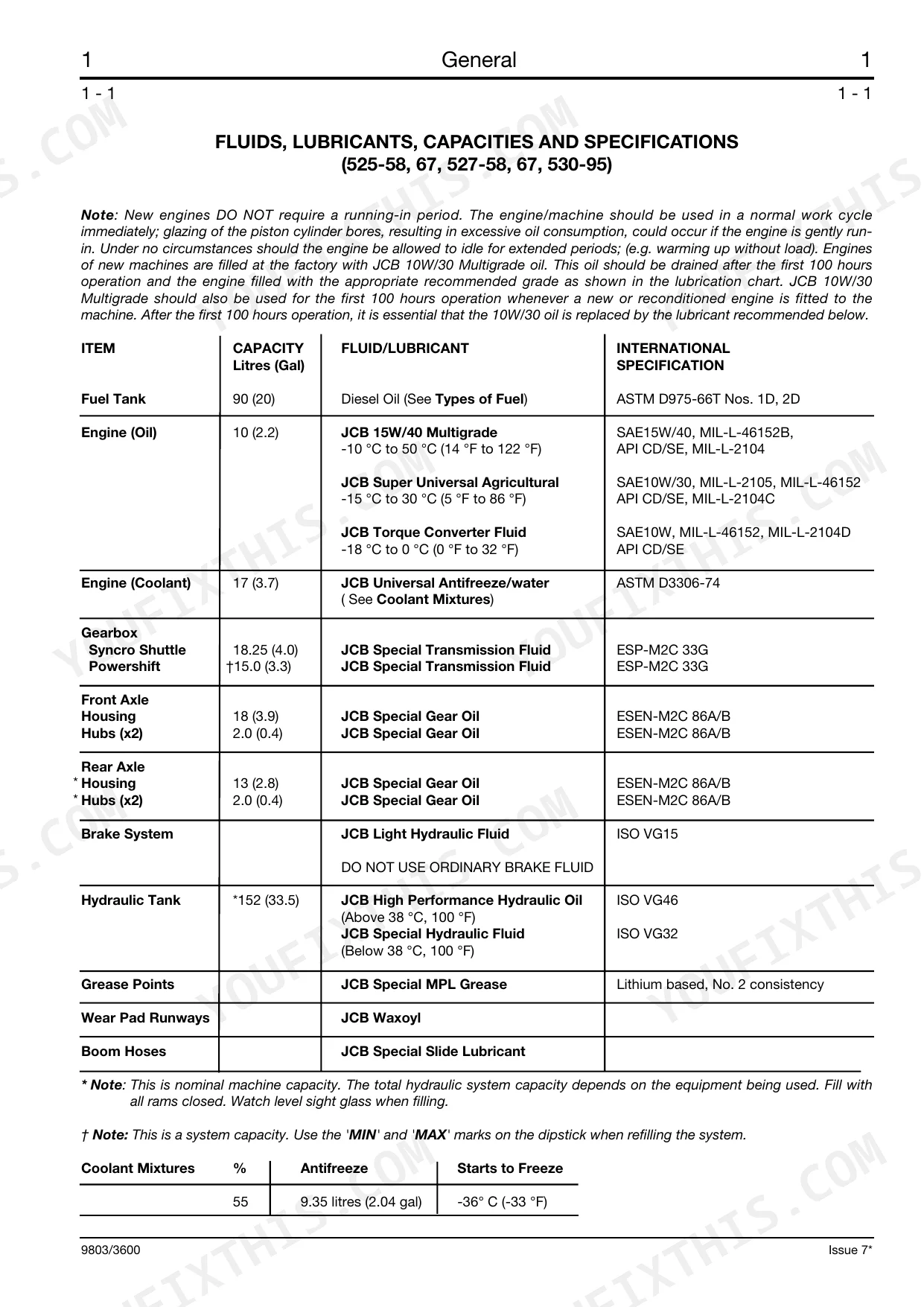
| Fuel Tank Capacity | 90 litres (20 gal) | p. 8 |
| Engine Oil Capacity | 10 litres (2.2 gal) | p. 8 |
| Hydraulic Tank Capacity | 152 litres (33.5 gal) | p. 8 |
| Coolant Mixture (Antifreeze) | 9.35 litres (2.04 gal) for 55% | p. 8 |
| 525-58, 67, 527-58, 67, 530-67 & 535-67 | ||
| Main Relief Valve (MRV) operating pressure | 220 bar (224 kgf/cm2, 3200 lbf/in2) | p. 36 |
| Hydraulic pump flow at max. engine rev/min (at system pressure) | 84.0 litres/min (18.5 UK gal/min, 22.2 US gal/min) | p. 36 |
| 530-120 | ||
| Hydraulic pump flow at max. engine rev/min (at system pressure) | 105.0 litres/min (23.0 UK gal/min, 27.6 US gal/min) | p. 37 |
| 525-58, 67, 527-58, 67 and 530-67, 95, 110 | ||
| Steer ram bore | 50 mm (1.97 in) | p. 613 |
| 530-120 & 537-120, 130 | ||
| Steer ram bore | 60 mm (23.62 in) | p. 613 |
| 525-58/67, 527-58/67 & 530-95 | ||
| Hydraulic tank capacity | 152 Litres (33.5 Gal) | p. 8 |
| Hydraulic fluid type (Above 38 °C, 100 °F) | JCB High Performance Hydraulic Oil ISO VG46 | p. 8 |
JCB 525–537 Common Problems This Manual Covers
Boom cracking at chassis pin mounts
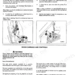
Forum users report booms cracking around the chassis pivot pins on poorly serviced machines. The Body and Framework section covers boom shimming and the pivot points where wear and stress build up.
Manual Section: Body and Framework p. 176Steering drifts out of alignment
Steering that wanders or will not self-center points to linkage wear or a hydraulic steering fault. The Hydraulic Steering section covers the flow regulating valve and steering pump service.
Manual Section: Hydraulic Steering p. 611Sudden loss of drive
A 525-67 or similar machine can develop a sudden drive fault after years of reliable use. The Transmission section provides Syncro Shuttle and Powershift technical data, the recovery procedure, and oil checks.
Manual Section: Transmission p. 383Weak hydraulics with normal oil level
Hydraulic functions can weaken even when the reservoir looks full, often from pump wear or an internal fault. The Hydraulics section gives the pump flow figures and the main relief valve pressure of 220 bar.
Manual Section: Hydraulics p. 34Neglected greasing and pivot wear
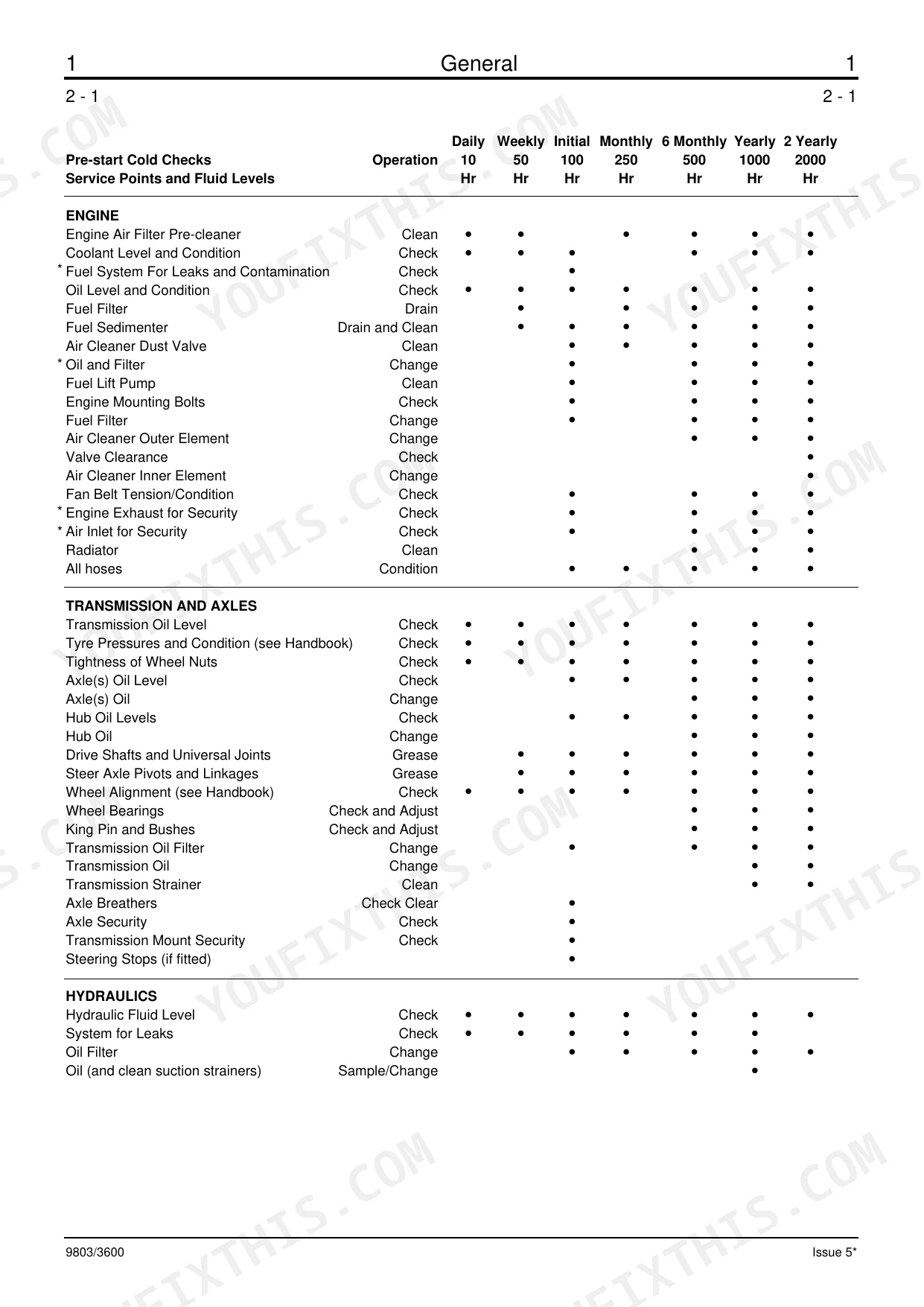
Skipped lubrication at the boom pivots, pins, and bushings leads to structural and wear failures. The General section lists the greasing points and service schedules to keep ahead of them.
Manual Section: General p. 3Parking brake will not hold
A parking brake that drags or slips needs adjustment or new parts. The Brakes section covers parking brake adjusting, testing, and dismantling for these models.
Manual Section: Brakes p. 579Frequently Asked Questions
Which models and years does this manual cover?
It covers the JCB 500 Series telehandlers from serial number 561001, including the 525-58/67, 527-58/67, 530-67/95/110/120, 535-67, 537-120, and 537-130 and their option variants, produced from 1989 to 1994.
What engine do these machines use?
They are fitted with the Perkins 1000 Series four cylinder engine. The Engine section covers technical data, the oil and fuel filters, fuel pump, bleeding, the cooling system, and the alternator drive belt. p. 357
What is the wheel nut torque?
The Axles section specifies a road wheel nut torque of 680 Nm (500 lbf ft), along with front axle weight and axle technical data for each model. p. 521
Does it give the hydraulic relief valve pressure?
Yes. The Hydraulics section lists the main relief valve pressure of 220 bar (3200 lbf/in2) for the 525-58/67, 527-58/67, 530-67, and 535-67 machines. p. 34
What format is this manual in?
Searchable PDF, delivered instantly. The full 736-page 525-58 Service Manual downloads the moment payment clears, ready to open on a laptop, tablet, or shop-floor phone.
Am I able to print pages from this manual?
Absolutely. No DRM or copy protection. Print the whole manual or just the pages you need. Any home or office printer works.
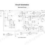
Are hydraulic system diagrams in this JCB 525-58 & variants Service Manual?
Yes. Complete hydraulic schematics are included, with flow diagrams, valve configurations, and pressure specifications.
Reviews
There are no reviews yet.