


This JCB Service Manual covers the 505-19, 505-22, 506-36, 508-40, 510-40, and 506B telehandlers of the 500 Series, publication number 9803/3600U. Across 701 pages it documents every major system on these machines, from the hydraulics and the PlaceAce and Servo control systems to the engine, transmission, axles, brakes, hydraulic steering, and electrics.With it you can diagnose a hydraulic fault, set the main relief valve pressures, shim the boom, service the Syncro Shuttle or Powershift transmission, bleed the brakes, and trace wiring through the electrical section. Technical data tables give torque figures, fluid capacities, and pressure settings for each model variant, so you can match the procedure to your exact serial number.It is the factory workshop reference for owners and mechanics keeping these Loadall telehandlers running.
What's Inside This JCB 505–510 Manual
| System | Pages | Key Topics |
|---|---|---|
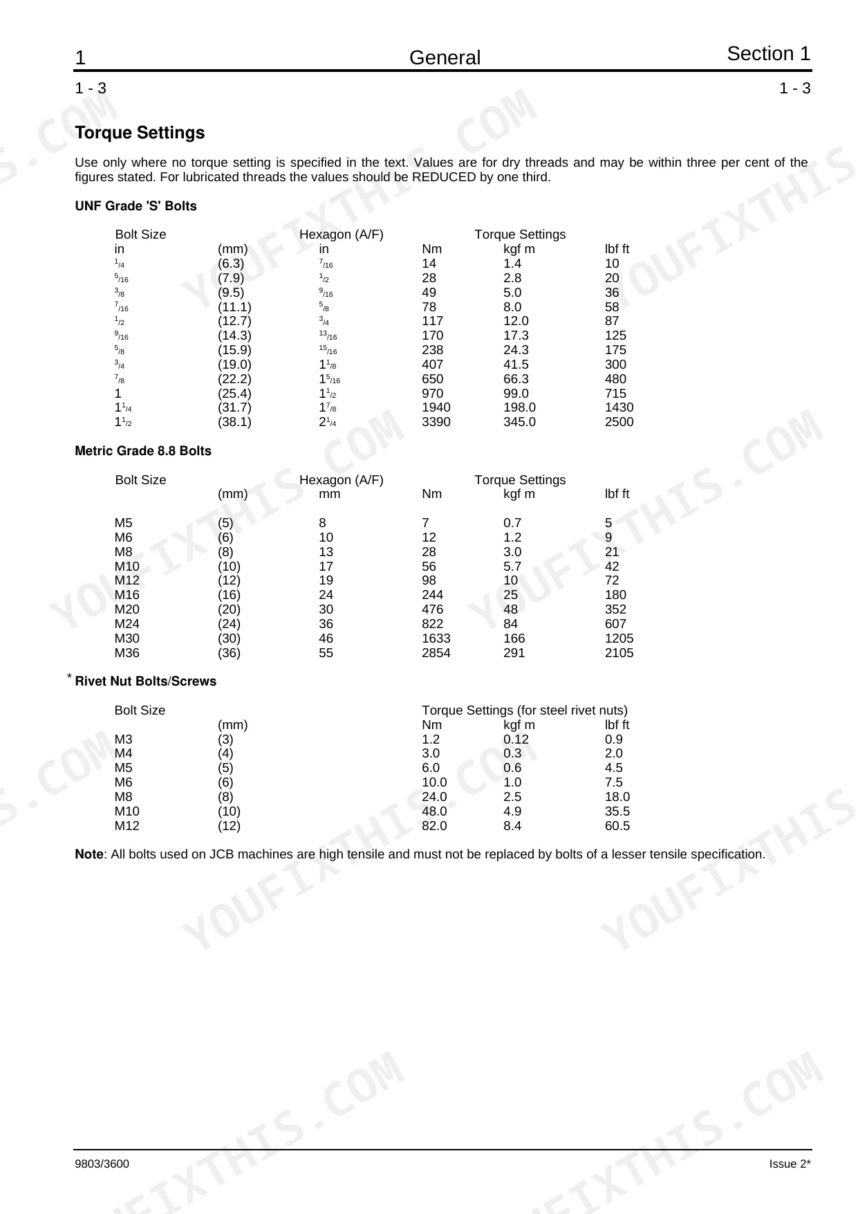
| General | 5-30 | Fluids, Lubricants, Capacities & Specifications (-: 505-19/22, 506-36, 508-40 & 510-40, 506B, Torque Settings), Service Schedules |
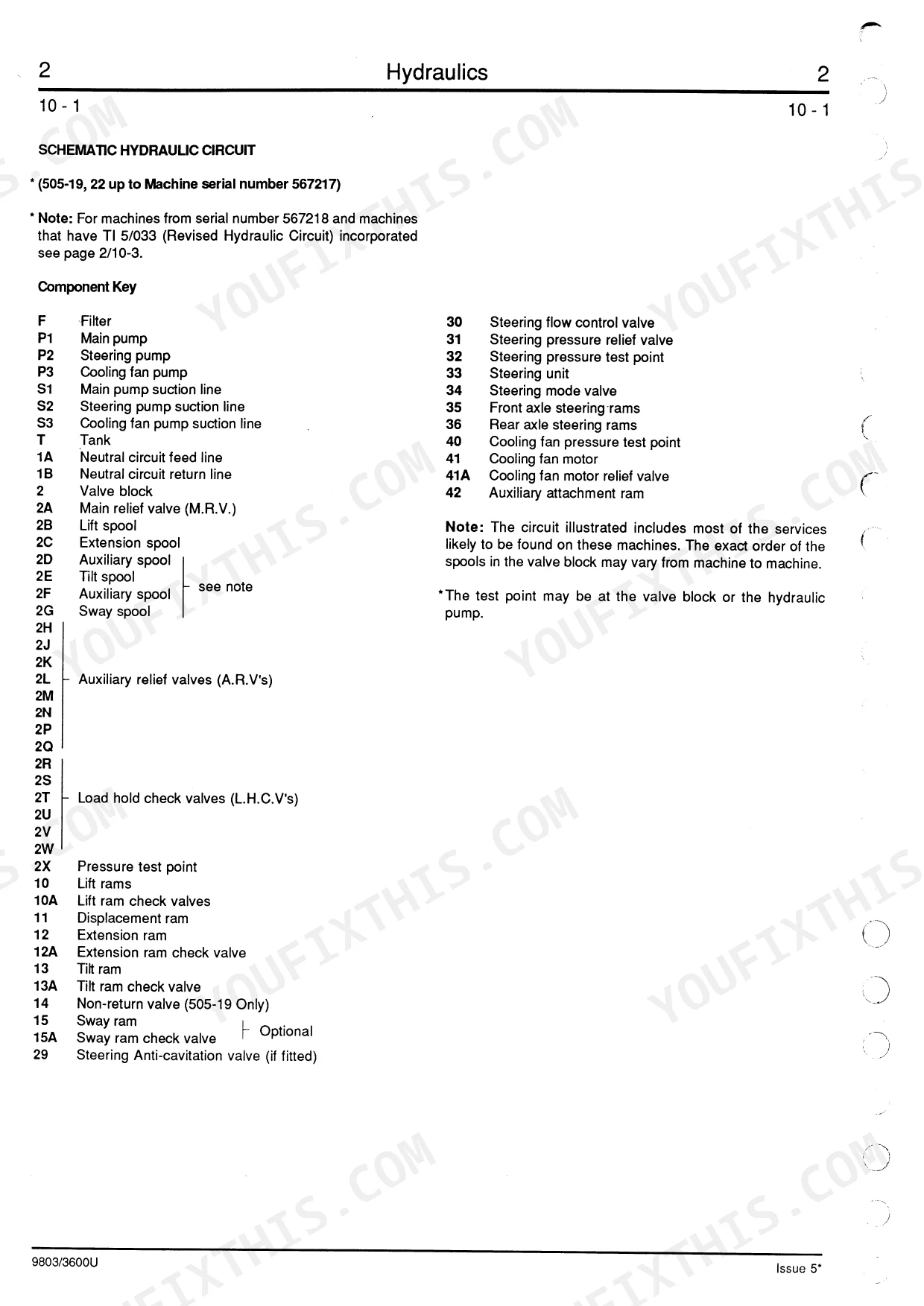
| Hydraulics | 31-171 | Technical Data (-: 525-19/22, 508-40, 506-36, 510-40, 506B), Hydraulic Fluid Level & Filter (-: 505-19/22, 506-36 & Early 508-40, 508-40 Later Machines |
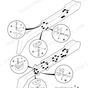
| Body and Framework | 172-226 | Boom Shimming - Typical Method, Boom Shimming - 505-19/22, Boom Shimming - 506-36, Boom Shimming - 508-40, 510-40, Boom Shimming - 506B, Inner Extension Ram Wear Pads - 508-40 |
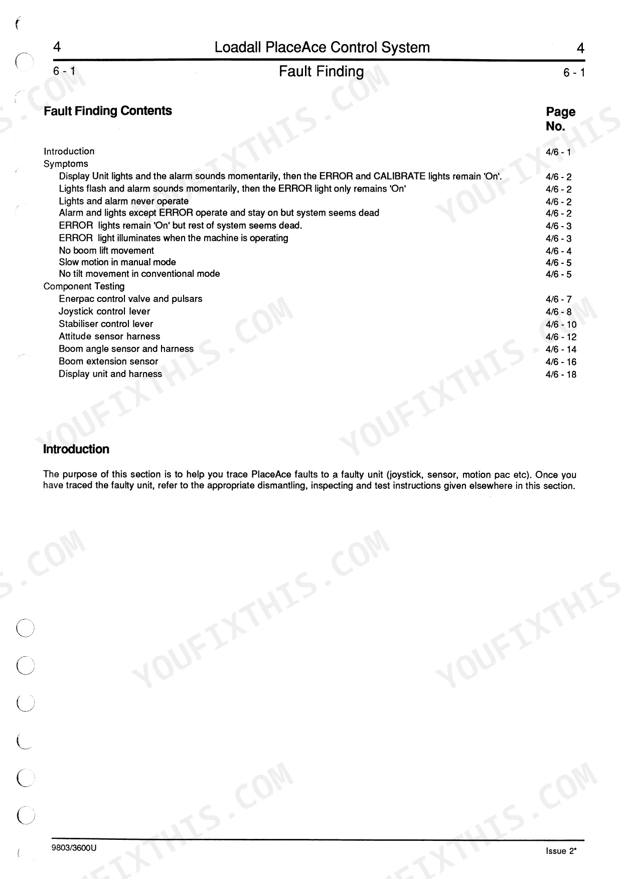
| PlaceAce Control System | 227-290 | Technical Data (-: 508-40, 510-40), Control System Description, Valve Block Operation, Pulsar Block Operation, Valve Block Removal & Replacement |
| Servo Control System | 291-349 | Technical Data (-: 505-19/22, 506-36, 508-40), Basic Servo Control System Description (- 505-19/22), Servo Control System Description (- 506-36, Valve Block Operation |
| Engine | 350-372 | Technical Data, Engine Cover, Engine Oil Filter, Fuel Filter, Fuel Pump, Bleeding, Cooling System, Alternator Drive Belt |
| Transmission | 373-507 | Syncro Shuttle Technical Data, Syncro Shuttle General Description, Powershift Technical Data, Recovery Procedure, Checking & Changing Oil |
| Axles | 508-562 | Technical Data (-: 505-19/22, 508-40, 510-40, 506-36 & 506B), Road Wheel Removal & Replacement, Water Ballast Tires, Front Axle Breather Removal & Replacement, Axle Oil Level |
| Brakes | 563-582 | Technical Data (-: 505-19/22, 508-40, 510-40, 506-36, 506B), Parking Brake Adjusting & Testing, Parking Brake Dismantling & Assembly, Brake System Bleeding |
| Hydraulic Steering | 583-634 | Technical Data, Flow Regulating Valve Operation, Tandem Steering/Fan Pump Dismantling & Assembly, Steering/Fan Pump Removal & Replacement |
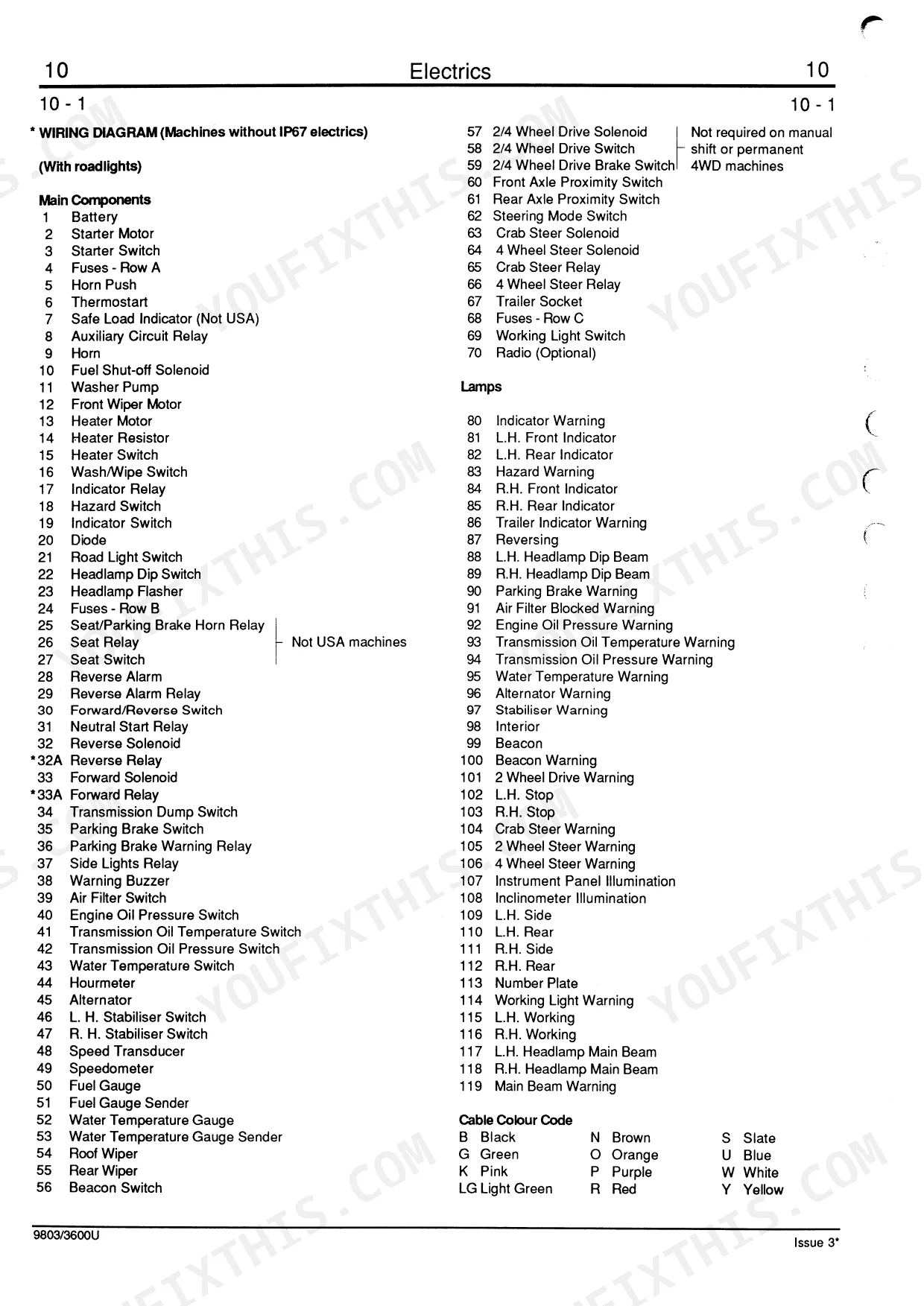
| Electrics | 635-676 | Introduction, Technical Data, Fuses, Relay Location, Test Methods, Batteries Testing, Alternator (-: Precautions, Testing, Removal & Replacement, Dismantling & Assembly) |
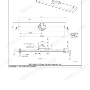
| Service Tools | 677-690 | Numerical List, Section List, Sealing and Retaining Compounds |
| Boom Float, Return to Dig Option | 691-701 | Numerical List, Schematic Hydraulic Circuit, Wiring Diagram, Relay Location, Fault Finding, Micro Switch Adjustment, Proximity Switch Adjustment |
Quick Reference Specifications
| Specification | Value | Page |
|---|---|---|
| All Models | ||
| Wheel Studs Torque | 680 Nm | p. 513 |
| Axle Mounting Bolts Torque | 56 Nm | p. 521 |
| Electrical System Voltage | 12 volts, negative earth | p. 639 |
| Alternator Maximum Output | 65 amp | p. 639 |
| Normal Engine Coolant Temperature | 80-85 °C (175-185 °F) | p. 359 |
| 505-19, 505-22 | ||
| Main Relief Valve (M.R.V.) Operating Pressure | 220 bar (3200 lbf/in²) | p. 33 |
| Hydraulic Filter Filtration Size | 25 microns (0.001 in) | p. 33 |
| Hydraulic Filter Relief Valve Setting | 1.05 bar | p. 33 |
| Fuel Tank Capacity | 24 US Gal (90 Litres) | p. 6 |
| Engine Oil Capacity | 2.6 US Gal (10 Litres) | p. 6 |
| 508-40 | ||
| Main Relief Valve (M.R.V.) Operating Pressure | 241 bar (3500 lbf/in²) | p. 34 |
| 506-36 | ||
| Main Relief Valve (M.R.V.) Operating Pressure | 241 bar (3500 lbf/in²) | p. 35 |
JCB 505–510 Common Problems This Manual Covers
Boom or drive functions cut out
Owners report lift, boom, or drive functions becoming intermittent or dropping out after startup on these 500 Series machines. The Electrics section covers the wiring diagrams, test methods, and relay locations needed to trace the fault.
Manual Section: Electrics p. 635Weak or slow hydraulic response
Slow lift and low pushing force often point to worn pump output or an incorrect main relief valve setting. The Hydraulics section gives the M.R.V. pressures and pump procedures for each model.
Manual Section: Hydraulics p. 31Overheating or repeated fluid top-offs
Machines that need constant coolant or oil top-offs, or that run hot, usually have a wrong fluid grade, a leak, or contamination. The General section lists the correct fluids, lubricants, and capacities per model.
Manual Section: General p. 5Transmission or drive malfunction
A sudden loss of drive or erratic shifting on a Syncro Shuttle or Powershift machine calls for repair-level diagnostics. The Transmission section covers the technical data, the recovery procedure, and oil checks.
Manual Section: Transmission p. 373Boom wear pad play
As the telescopic boom wears, excessive play develops between the boom sections and their wear pads. The Body and Framework section details boom shimming for each model and inner extension ram pad wear.
Manual Section: Body and Framework p. 172Parking brake will not hold
A parking brake that drags or fails to hold usually needs adjustment or new friction parts. The Brakes section covers parking brake adjusting, testing, dismantling, and system bleeding.
Manual Section: Brakes p. 563Steering drifts or feels heavy
Wandering steering or heavy effort can come from the flow regulating valve or a worn steering pump. The Hydraulic Steering section covers valve operation and pump removal and overhaul.
Manual Section: Hydraulic Steering p. 583Frequently Asked Questions
Which JCB models does this manual cover?
It covers the 500 Series 505-19, 505-22, 506-36, 508-40, 510-40, and 506B telehandlers, including two-stage and three-stage boom machines, under publication number 9803/3600U.
What is the main relief valve pressure for these machines?
The hydraulic main relief valve is set to 220 bar (3200 lbf/in2) on the 505-19 and 505-22, and 241 bar (3500 lbf/in2) on the 508-40, 506-36, and 510-40. The Hydraulics section lists each figure. p. 31
Does it include the wheel stud torque?
Yes. The Axles section gives the wheel stud torque of 680 Nm, along with axle technical data and road wheel removal and replacement steps. p. 508
Does it cover the electrical system?
Yes. The Electrics section documents the 12 volt negative earth system, the 65 amp alternator, fuses, relay locations, and test methods for diagnosing faults. p. 635
How will I receive this Service Manual?
A 701-page Service Manual in searchable PDF format, available the moment you complete checkout. View on computer, tablet, or phone — no shipping wait.
Can I print specific sections of this Service Manual?
Yes. The PDF has no DRM restrictions — print any page or section you need for your shop. Works with any standard printer.
Are electrical wiring diagrams included in this JCB 505-19 & variants manual?
Yes, this JCB 505-19 & variants Service Manual includes complete electrical wiring diagrams, wire routing, and connector pinouts.
Reviews
There are no reviews yet.