


Part of the JCB Repair Manuals.
This is the JCB service manual for the TM310, TM310S, TM310WM, and TM320 telescopic wheeled loaders, publication 9803/9520-9, covering machines from serial number 1314700 and model years 2004 to 2012. These handlers run the JCB Dieselmax engine.At 690 pages it is a full workshop manual arranged by lettered section: general information and torque settings, care and safety, routine maintenance, body and framework with the boom and cab, electrics, hydraulics, powershift transmission, brakes, steering, the engine, and the network systems covering CANbus, the monitoring system, and electronic fault codes.Use it to service the machine on schedule, set boom wear pad clearances, rebuild hydraulic and transmission components, trace electrical faults with the schematics and diagnostic tools, and read fault codes. Torque settings and technical data open each section.
What's Inside This JCB TM310–TM320 Series Manual
| System | Pages | Key Topics |
|---|---|---|
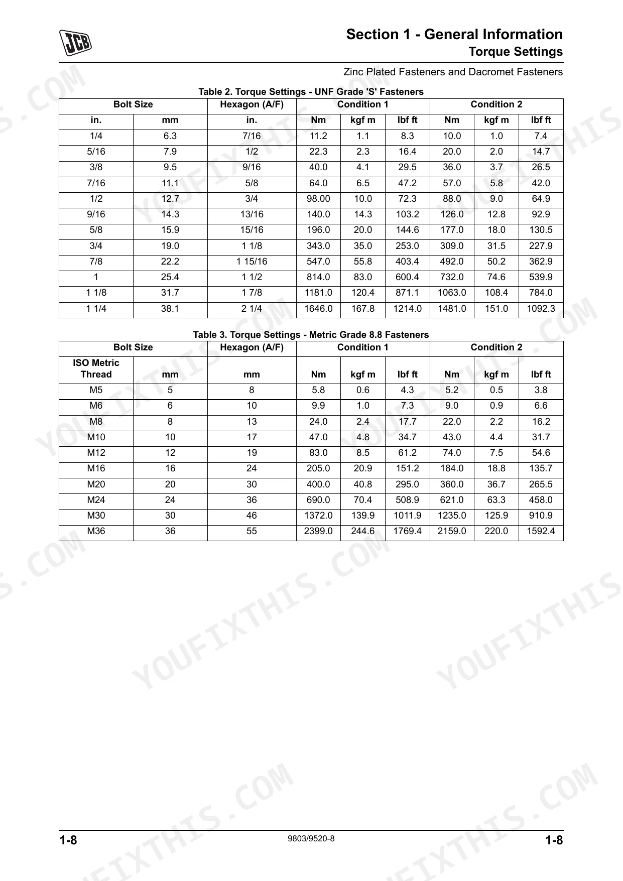
| General Information | - | Machine Model and Serial Number, Torque Settings, Service Tools, Service Consumables, Terms and Definitions |
| Care and Safety | - | Safety Notices, General Safety, Operating Safety, Maintenance Safety, Safety Labels |
| Routine Maintenance | - | Service Schedules, Fluids, Lubricants and Capacities, Prepare the Machine for Maintenance, Checking for Damage, Greasing, Electrical System, Engine |
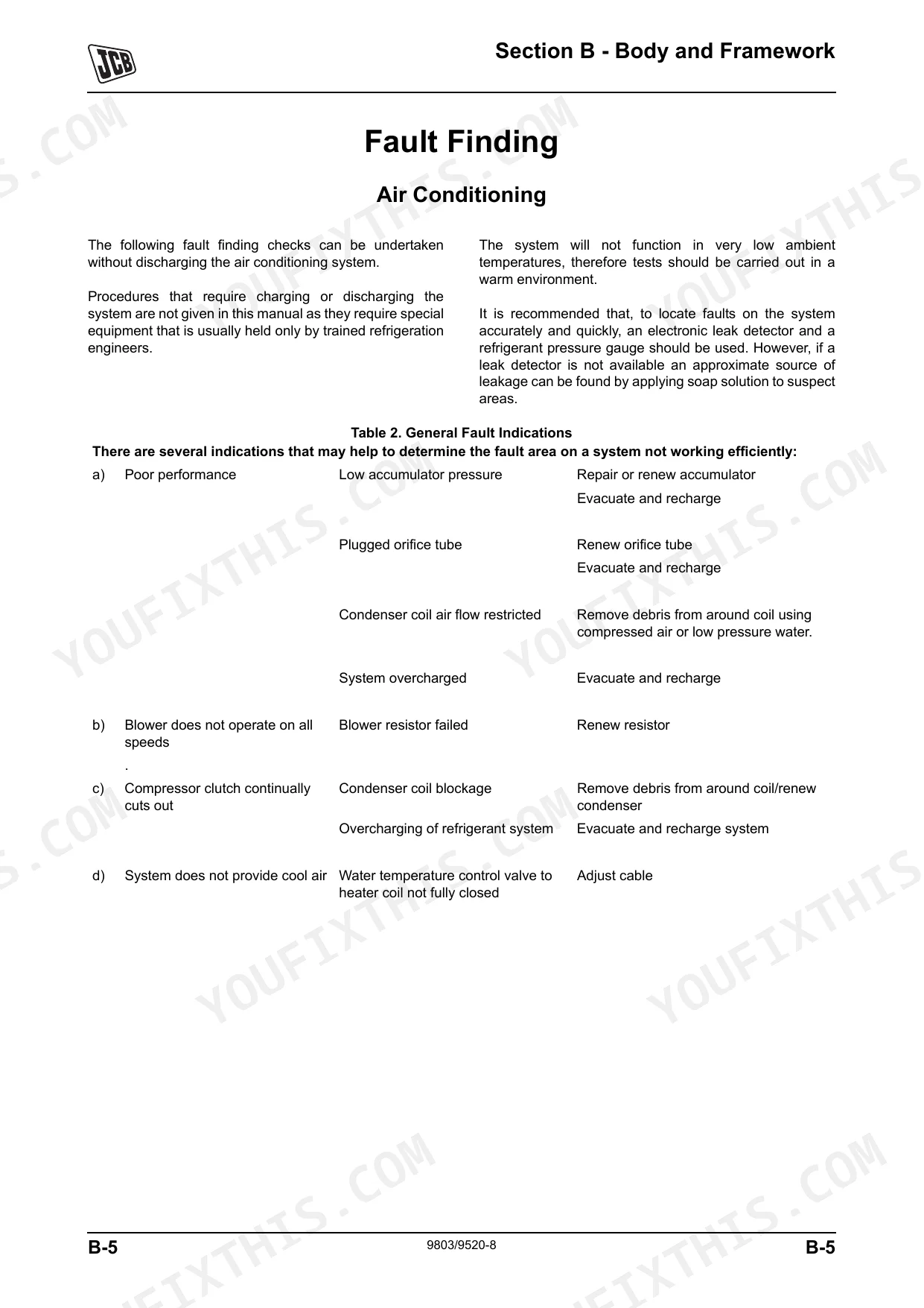
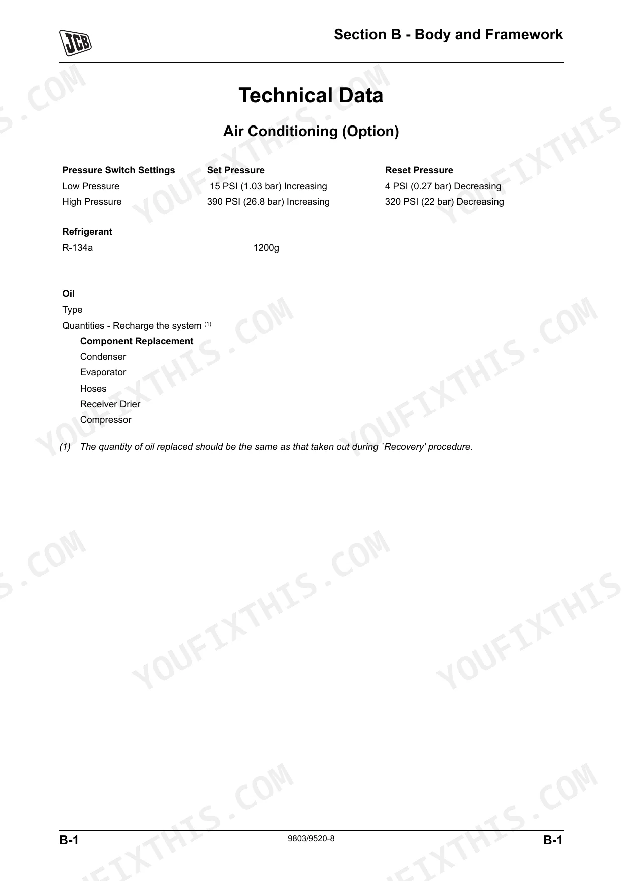
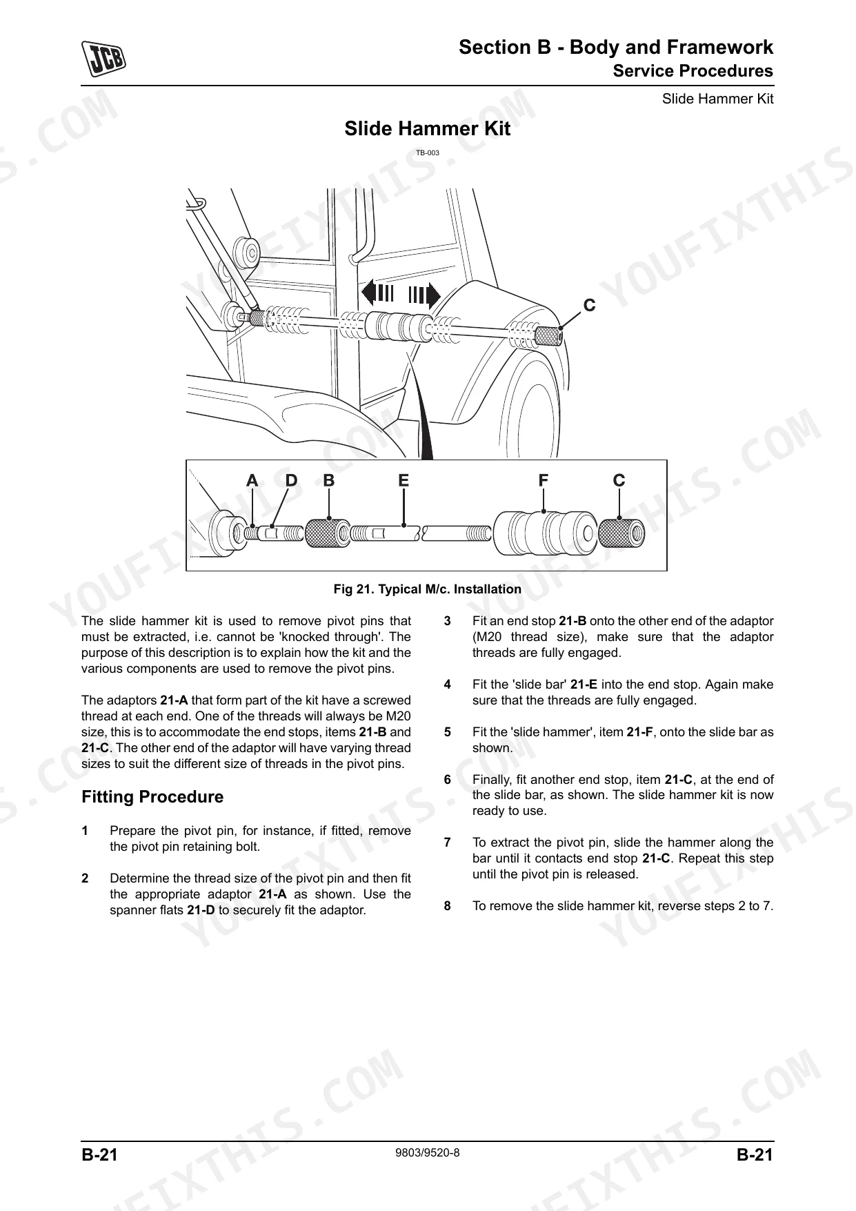
| Section B - Body and Framework | - | Air Conditioning Technical Data, Load Moment Indicator Basic Operation, Rivet Nuts Service Procedures, Boom Removal and Replacement, Cab Removal and Replacement |
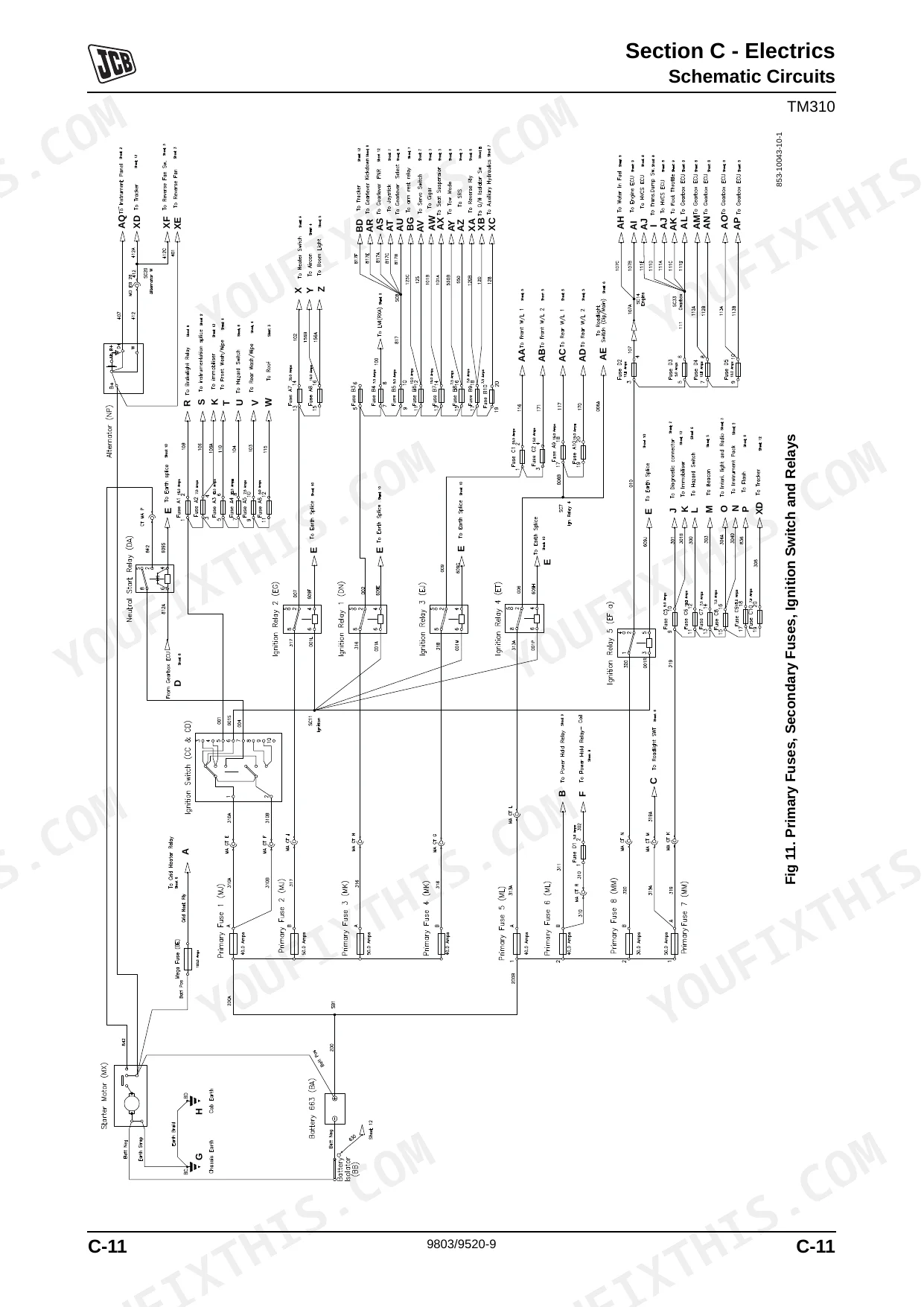
| Section C - Electrics | - | General Electrical Data, Fuses and Relays, Schematic Circuits, Using a Multimeter, Battery Service Procedures, Wiring Harness Repair |
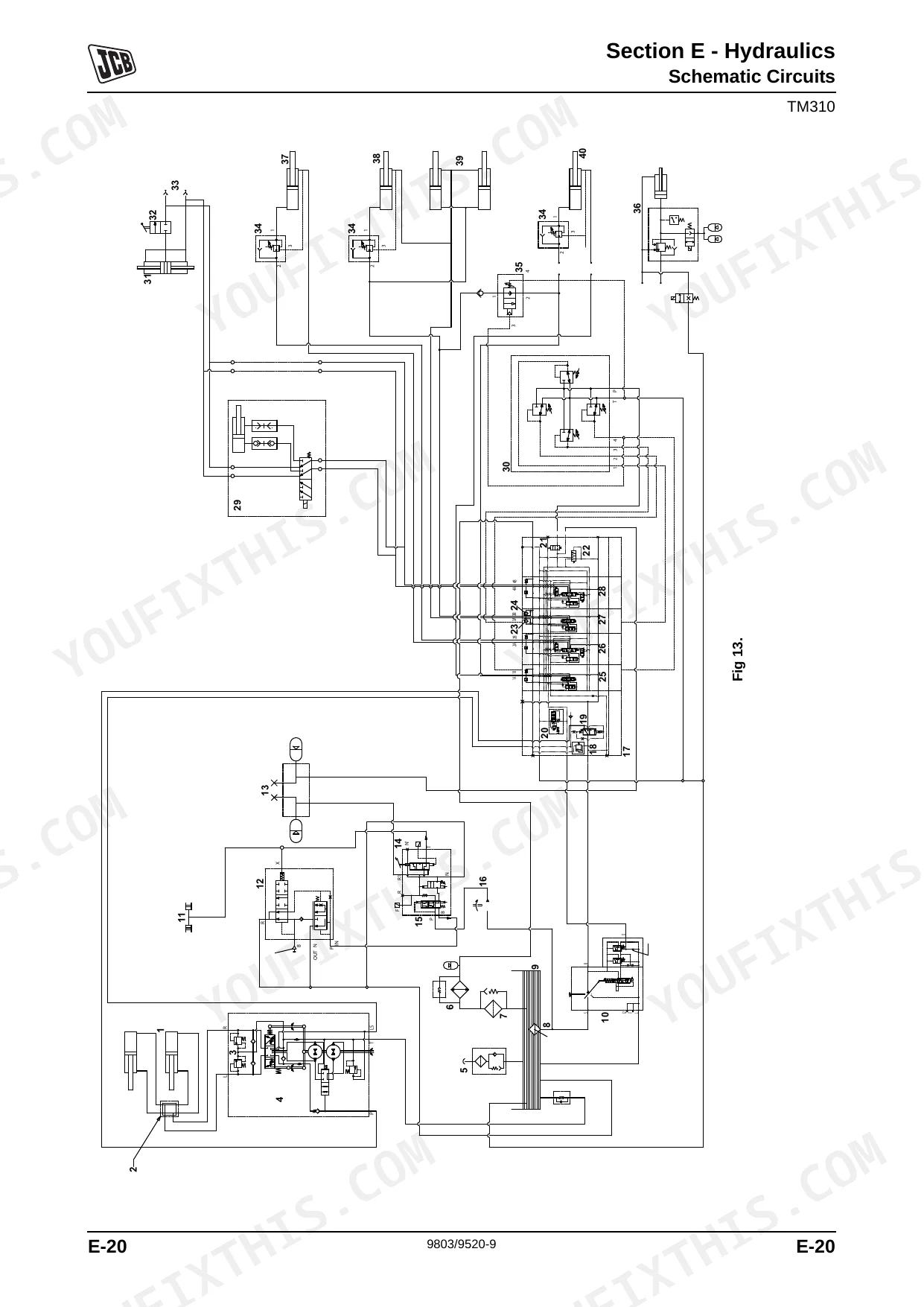
| Section E - Hydraulics | - | Main Hydraulic Pump Technical Data, Control Valve Block Basic Operation, Circuit Descriptions, Flow and Pressure Tests, Hydraulic Rams Removal and Replacement |
| Section F - Transmission | - | Tyre Pressures and Sizes, Powershift Gearboxes Technical Data, Torque Converter Basic Operation, Electrical Connections, Fault Finding, Front Axle Removal and Replacement |
| Section G - Brakes | - | Park Brake Gearbox Integral, Brake Pump Removal and Replacement, Brake Valve Removal and Replacement, Bleeding the Braking System |
| Section H - Steering | - | Bleeding the System, Hydraulic Pressure Tests, Steer Rams Removal and Replacement, Hydraulic Steer Unit Removal and Replacement, Steering Manifold Removal and Replacement |
| Section K - Engine | - | Basic Engine Data, Silencer Removal and Replacement, Cooling Pack Removal and Replacement, Engine ECU Circuit Descriptions, Engine Installation, Engine Assembly |
| Section M - Network Systems | - | CANbus Communications System, Electronic Monitoring System, Electronic Fault Codes, Servicemaster Tools, Jcb 4.4L Tier 3 Se Diagnostics Tool, ShiftMaster Diagnostics 2.3 |
Quick Reference Specifications
| Specification | Value | Page |
|---|---|---|
| Wheel nut torque (Front) | 680 Nm (500 lbf ft) | p. 130 |
| Wheel nut torque (Rear) | 680 Nm (500 lbf ft) | p. 130 |
| Lower inside face of outer boom to underside of inner boom Standard | 17 mm | p. 184 |
| Lower inside face of outer boom to underside of inner boom (add shims if below) | 15 mm (0.59 in) | p. 184 |
| Articulated joint vertical pivot bushes replacement criteria | Renew if any play is detected | p. 193 |
| Articulated joint nominal dimension | 202 mm (7.953 in) | p. 194 |
| BSP Adaptor Torque (1/4 in) | 18.0 Nm | p. 16 |
| BSP Adaptor Torque (3/8 in) | 31.0 Nm | p. 16 |
| Hydraulic filter cap torque | 40 Nm (29.5 lbf ft) | p. 372 |
| Alternator nominal output | 95 Amp | p. 237 |
| Alternator mounting bolts torque | 47 Nm (4.8 kgf m 34.7 lbf ft) | p. 291 |
| Boom Lift Cycle Time (unladen) | 6.0 Seconds | p. 340 |
JCB TM310–TM320 Series Common Problems This Manual Covers
Headstock cracks at the center eyes
The TM310 and TM320 headstock has a known weak point at the center eyes that cracks or develops play under repeated high loads. The body and framework section covers the boom, its wear pads, and removal and replacement.
Manual Section: Section B - Body and FrameworkWeak or slow hydraulic functions
Slow boom and loader response points to pump wear, valve faults, leaks, or contamination. The hydraulics section covers the main pump, control valve block, and flow and pressure tests.
Manual Section: Section E - HydraulicsFault codes and electronic faults
CANbus and monitoring faults show up as electronic fault codes that need the diagnostic tools to read. The network systems section covers the CANbus communications and electronic fault codes.
Manual Section: Section M - Network SystemsTransmission or powershift problems
Powershift and torque converter faults cause poor drive and shifting. The transmission section covers the powershift gearboxes, electrical connections, and fault finding.
Manual Section: Section F - TransmissionHard starting or engine running faults
Starting and running problems need the engine and its ECU checked. The engine section covers basic engine data, the cooling pack, and the engine ECU circuit descriptions.
Manual Section: Section K - EngineElectrical and control faults
Sensor, switch, and wiring faults need systematic tracing. The electrics section covers fuses and relays, schematic circuits, and using a multimeter.
Manual Section: Section C - ElectricsFrequently Asked Questions
Which models and years are covered?
The manual covers the JCB TM310, TM310S, TM310WM, and TM320 telescopic wheeled loaders from serial number 1314700, spanning 2004 to 2012, all with the JCB Dieselmax engine. It is publication 9803/9520-9.
How do I get it?
It is an instant PDF download after purchase, with no shipping.
What is the wheel nut torque?
The front and rear wheel nuts are torqued to 680 Nm (500 lbf ft), a figure verified against the manual. Torque settings are listed at the front of the manual. p. 130
What is the boom wear pad bolt torque?
The boom wear pad retaining bolts are torqued to 60 Nm (44 lbf ft). Setting the boom wear pads and their clearances is covered in the body and framework section. p. 189
How quickly can I access this manual after buying?
This is a 690-page searchable PDF ready for immediate download. It works on any device, so you can pull it up on your phone while you're under the hood. No shipping, no waiting.
Can I print this manual?
Yes. The PDF carries no DRM restrictions, so print any page or section you need for the shop. It works with any standard printer.
Are there wiring harness diagrams in this JCB TM310–TM320 Series manual?
Yes, this JCB TM310–TM320 Series Service Manual includes complete electrical wiring diagrams, wire routing, and connector pinouts.

Reviews
There are no reviews yet.