

Part of the JCB Repair Manuals.
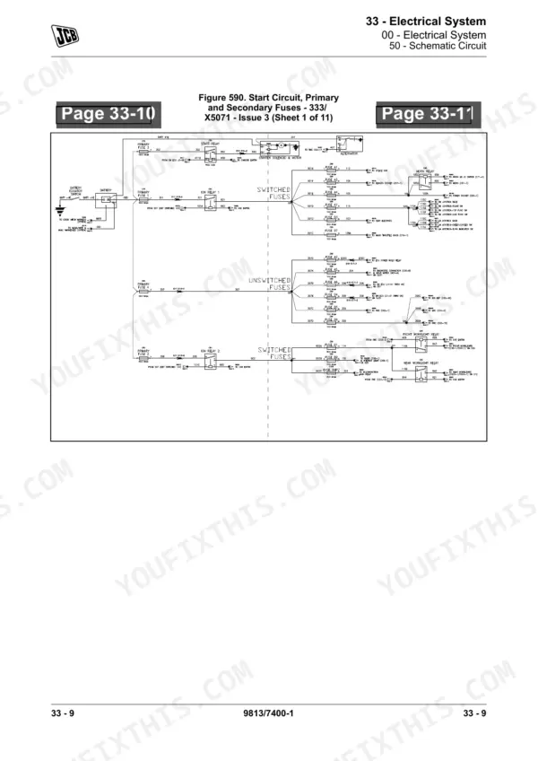
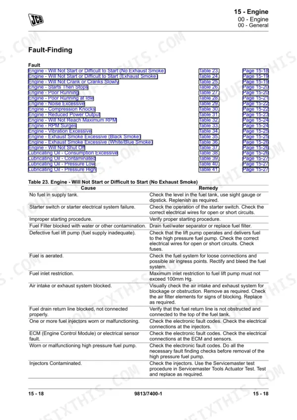
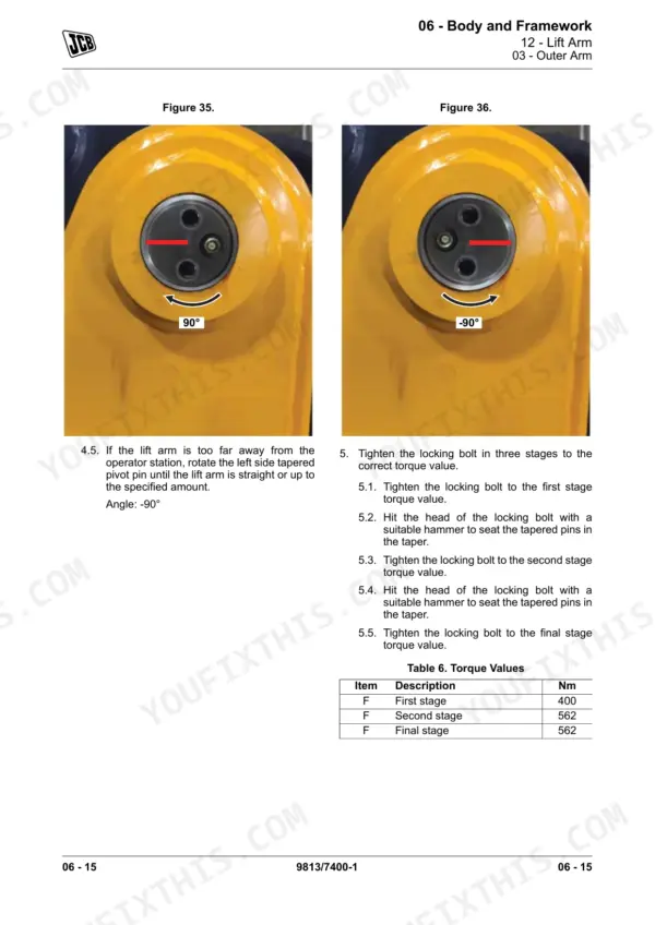
OEM EN-9813/7400 runs 1,364 pages on a single machine: the Teleskid skid steer loader, covering engine, driveline, hydraulics, electrical, and every attachment interface. Hydraulic schematics trace each circuit from charge pump to cylinder ram, and wiring diagrams map the chassis harnesses, EH control modules, and operator station circuits. Structured troubleshooting covers 40 Servicemaster fault codes with diagnostic detail, alongside rebuild procedures and torque tables spanning every major system. Lift arm tapered pivot pins stage at 400 Nm on the first pass, then 562 Nm final; main bearing bolts seat at 50 N·m before the bedplate sealant bead goes down. When your machine is grounded and a forum guess won't cut it, search any spec by keyword and take it to the bay.
Complete the set for your 3TS-8T, 3TS-8W
What's Inside This JCB 3TS-8T, 3TS-8W Manual
| System | Pages | Key Topics |
|---|---|---|
| Machine | 5-40 | Acronyms Glossary |
| Attachments, Couplings and Load Handling | 41-62 | Acronyms Glossary, Attachments (General), Lift Arm Quickhitch (General, Electronic Quickhitch), Shovel (General), Fork (General) |
| Body and Framework | 63-108 | Acronyms Glossary, Moveable Panel and Cover (General, Engine Compartment, Rear Cover), Lift Arm (General, Outer Arm, Inner Arm, Wear Pads, Stop Pad), Transportation Lock (General) |
| Operator Station | 109-150 | General, Window, Operator Seat, Seat Belt |
| Heating, Ventilating and Air-Conditioning (HVAC) | 151-202 | Heating, Ventilating and Air-Conditioning (HVAC), General, HVAC Unit, Evaporator, Expansion Valve, Compressor |
| Engine | 203-508 | General, Crankcase, Cylinder Head, Bedplate |
| Fuel and Exhaust System | 509-626 | General, Throttle Control System, Tank, Filter, Pre-Filter Element |
| Cooling System | 627-662 | General, Cooling Pack, Fan Motor, Expansion Tank |
| Brake System | 663-674 | Brake System General, Introduction, Park Brake |
| Driveline | 675-818 | General, Hub, Wheel, Wheel Drive Pump |
| Hydraulic System | 819-950 | Acronyms Glossary, General (Schematic: Symbols, Circuit), Tank (General, Suction Strainer, Breather), Filter (General, Main, Return Line), Charge Pump (General) |
| Electrical System | 951-1246 | General, Schematic Circuit, Earth Point, Battery, Isolator Switch, Battery Cable |
| Fasteners and Fixings | 1247-1274 | General, Screws, Bolts, Bearings |
| Consumable Products | 1275-1320 | General, Oil, Refrigerant, Grease |
| After Sales | 1321-1364 | Maintenance Schedules (General, Maintenance Intervals, Pre-Start Cold Checks, Service Points and Fluid Levels, Functional Tests and Final Inspection) |
Quick Reference Specifications
| Specification | Value | Page |
|---|---|---|
| Auxiliary Hydraulic Pressure Release Procedure | 1. Make the machine safe with the lift arm lowered. Refer to (PIL 01-03). 2. Turn off the engine. 3. Wearing a suitable glove, pull the relief pin ring outwards firmly to relieve pressure on all auxiliary couplers. Duration: 5s | p. 831 |
| Lift arm tapered pivot pins (First stage torque) | 400 Nm | p. 79 |
| Lift arm tapered pivot pins (Second stage torque) | 562 Nm | p. 79 |
| Bedplate to crankcase sealant bead dimension | 1.5mm | p. 260 |
| Main bearing bolts (1st Stage Torque) | 50N·m | p. 261 |
| Coarse Metric Grade 8.8 Fasteners (M10 bolt) | 47 N·m | p. 1260 |
| Coarse Metric Grade 10.9 Fasteners (M10 bolt) | 67 N·m | p. 1260 |
| Cylinder head gasket (replacement) | Discard the head gasket. Obtain the correct replacement head gasket. | p. 253 |
| Crankshaft Front Oil Seal (installation tolerance) | -0.5 -0/+0.5mm | p. 277 |
| Coarse Metric Grade 12.9 Fasteners (M10 bolt) | 80 N·m | p. 1260 |
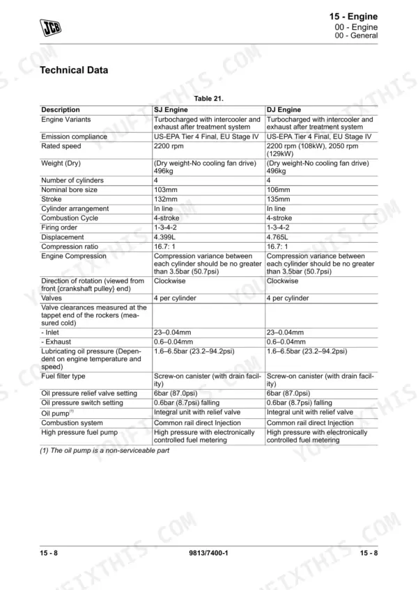
| Engine Dry Weight | 496 kg | p. 214 |
| Engine Compression Variance | no greater than 3.5 bar (50.7 psi) | p. 214 |