


Part of the JCB Repair Manuals.
This is the JCB service manual for the 805, 805B, 806B, 807B, and 808 tracked excavators, publication 9803/3150. It covers the full machine and the Perkins 4.248 and 6.354 series diesel engines, including turbocharged T6.354 units, along with the 2700 Series engines fitted to some builds.The 242 page manual is organised by system: general lubricants and service schedules, a large hydraulics section covering pumps, motors, and filtration, attachments, body and framework with the slew ring, track and slew gearboxes, tracks and running gear, the engine, and the electrical system with full circuit diagrams.Use it to service filters and belts on schedule, set track tension, torque the slew ring, trace hydraulic faults through the pumps and motors, and work through the wiring using the circuit diagrams for each model.
What's Inside This JCB 805–808 Manual
| System | Pages | Key Topics |
|---|---|---|
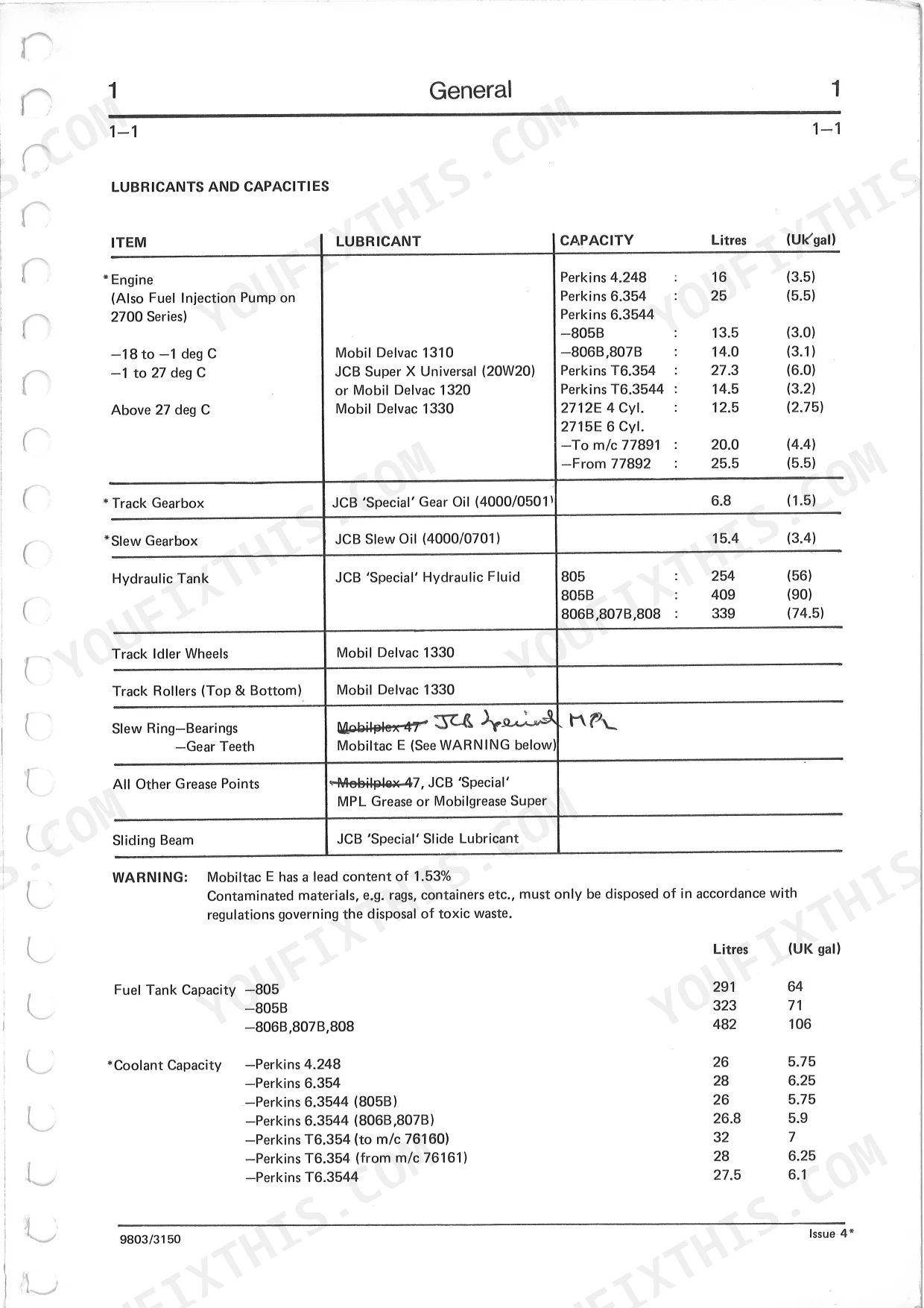
| General | 16-23 | Lubricants and Capacities, Service Schedule, Grease Points (All Pivot Pins, Each Slewing Ring Nipple and Rotary Coupling, Slewing Ring Teeth) |
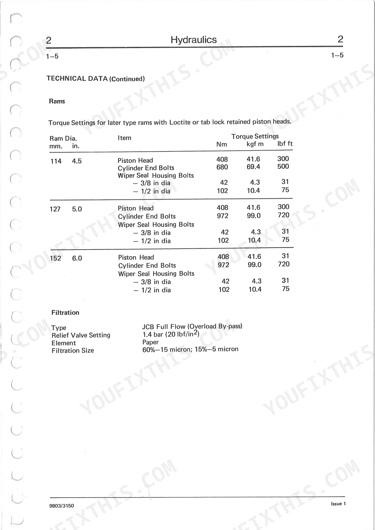
| Pumps and Motors (Commercial) | 24-39 | Hydraulic Filter (Early Type), Technical Data (Continued), Technical Data, Relief Valve Operating Pressures, River Maintenance Rig, Rams, Filtration, Filter Operation |
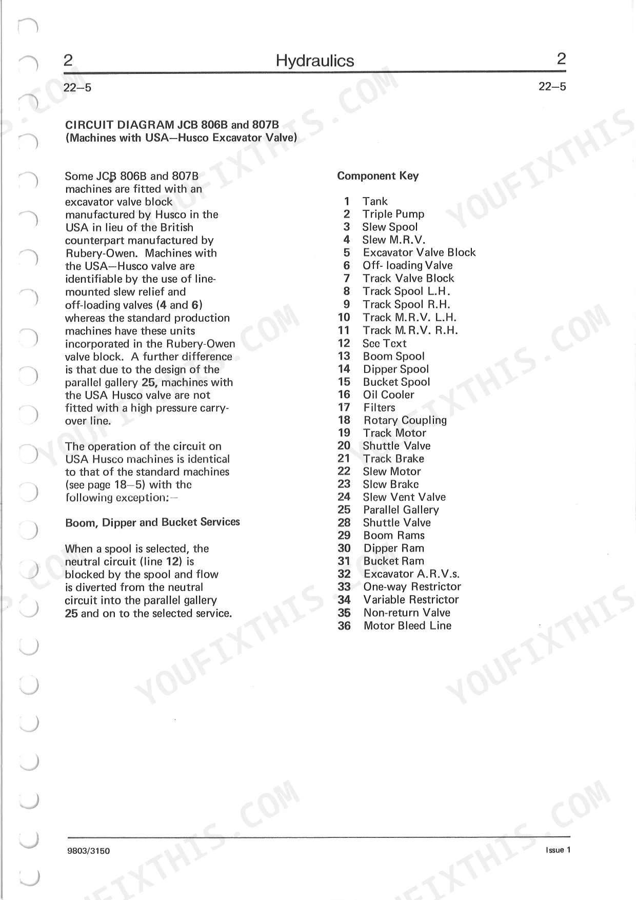
| Jcb 805B From M/C No. 200607 | 40-61 | Motor Spool (Husco) with Brake Vent Valve, Circuit Operation, Standard Spool Operation, Example, Method of Operation, Non-Return Valves, Typical Spool-Track, Excavator & Attachment Service Valves |
| Offloading Valve (in Valve Block-Pilot Operated) | 62-77 | Auxiliary Relief Valves (Rubery Owen and Husco), Relief Valves - Excavator & Attachment Service Valves, Excavator Relief Valve Operation, Auxiliary Relief Valve Operation, Operation, Valve Closed, Pilot Valve Opens, Dump Valve Opens |
| Pressure Testing | 78-93 | Offloading Valve Operation (Commercial), Operation, Off Loading Valve (Commercial), Dismantling and Assembly, When Assembling, Main Relief Valves-Track Block (Jcb 805, 806B |
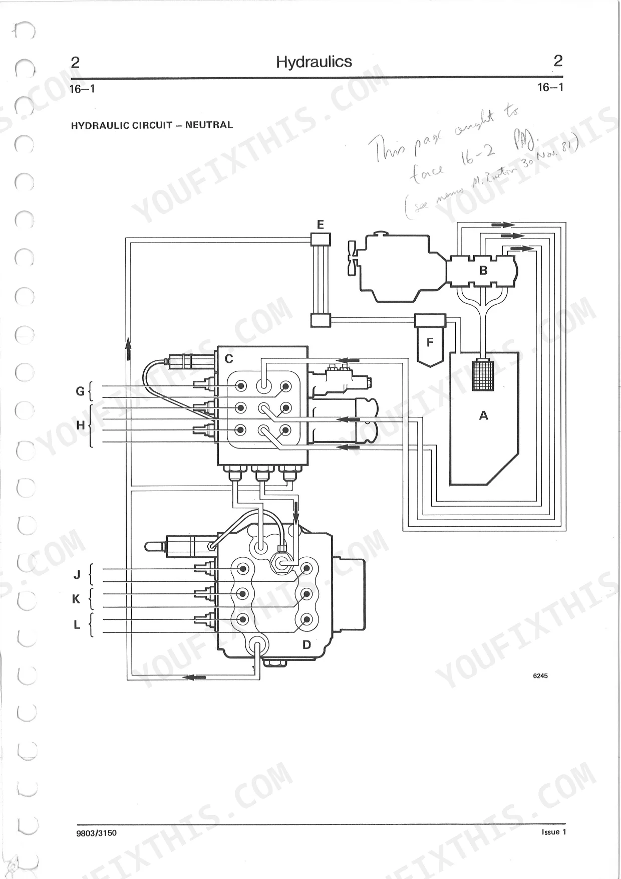
| Track & Slew Valve (Hamworthy) | 94-109 | Hydraulic Circuit - Excavator Operating, Track/Slew Valve Block - Slew Operating, Track/Slew Valve Block - Neutral Circuit, Hydraulic Circuit - Neutral, Hydraulic Circuit - Slew Operating, Track/Slew Valve Block - One Track Operating, Hydraulic Circuit - Tracks Operating, Track/Slew Valve Block - Two Tracks Operating |
| Variable Boom Drop Restrictor (From M/C No. 77307) | 110-125 | Pressure Testing (Hamworthy), Excavator Valve (Hamworthy), Track & Slew Valve (Hamworthy), Slew Relief Valve (a), When Dismantling, When Assembling, Offloading Valve (B), Non-Return Valves (C |
| Circuit Diagram Jcb 805B (to M/C No. 200147) | 126-141 | Rotary Coupling, Beam Clamp Control Valve (to M/C No. 200297), Beam Clamp Cylinder, Beam Clamp Operation, Dismantling and Assembly, When Dismantling, When Assembling, Port Connections |
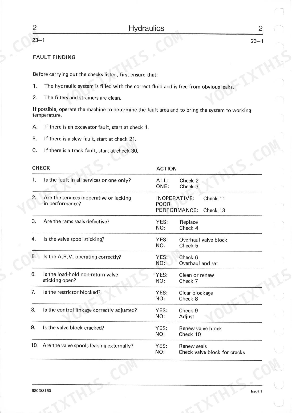
| Fault Finding (Continued) | 142-149 | Circuit Diagram Jcb 805B (From M/C No. 200148 to 200205), Neutral Circuit (Bold Line), Boom, Dipper and Bucket Services, Off-Loading Valve, Track Service, Slew Service, Beam Clamp |
| Attachments | 150-155 | Attachment Service Valve, Hose Connections, Grab Gearbox (Rotating Head) |
| Body & Framework | 156-167 | Cab (Glazing), Hydraulic Tilt Cab (System Bleeding), Slew Ring (When Replacing), Slew Ring Seal (Replacement) |
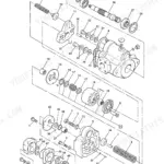
| Gearboxes | 168-188 | Track Gearbox, Slew Gearbox, Slew Gearbox Oil Level 805B, Track Gearbox (Primary Reduction), Track Gearbox (Secondary Reduction) |
| Track & Running Gear | 189-200 | Tracks (Inspect, Clean, Check, Adjust), Track (Removal and Replacement, When Removing, When Replacing), Rollers (Dismantling and Assembly) |
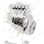
| Engine | 201-216 | Technical Data, Engine Oil Perkins, Engine Oil 2700 Series, Engine Oil Filter, Engine Fuel Filters, Engine Fuel Sediment Bowl, Engine Fuel Lift Pump, Engine Fuel System Perkins |
| Electrics | 217-236 | Technical Data, Circuit Diagram, Circuit Diagram 805, 806B, 807B, 808 (Main Components, Warning Lights, Lights, Cable Colour Code, Switches) |
Quick Reference Specifications
| Specification | Value | Page |
|---|---|---|
| Hydraulic Fault Reset Procedure | Not specified; manual provides fault finding checks and actions, not a general reset procedure. | p. 145 |
| Slew Ring Bolts Torque | 405 Nm (300 lbf ft) | p. 163 |
| Engine Oil Filter Replacement Interval | Every 200 Hours | p. 204 |
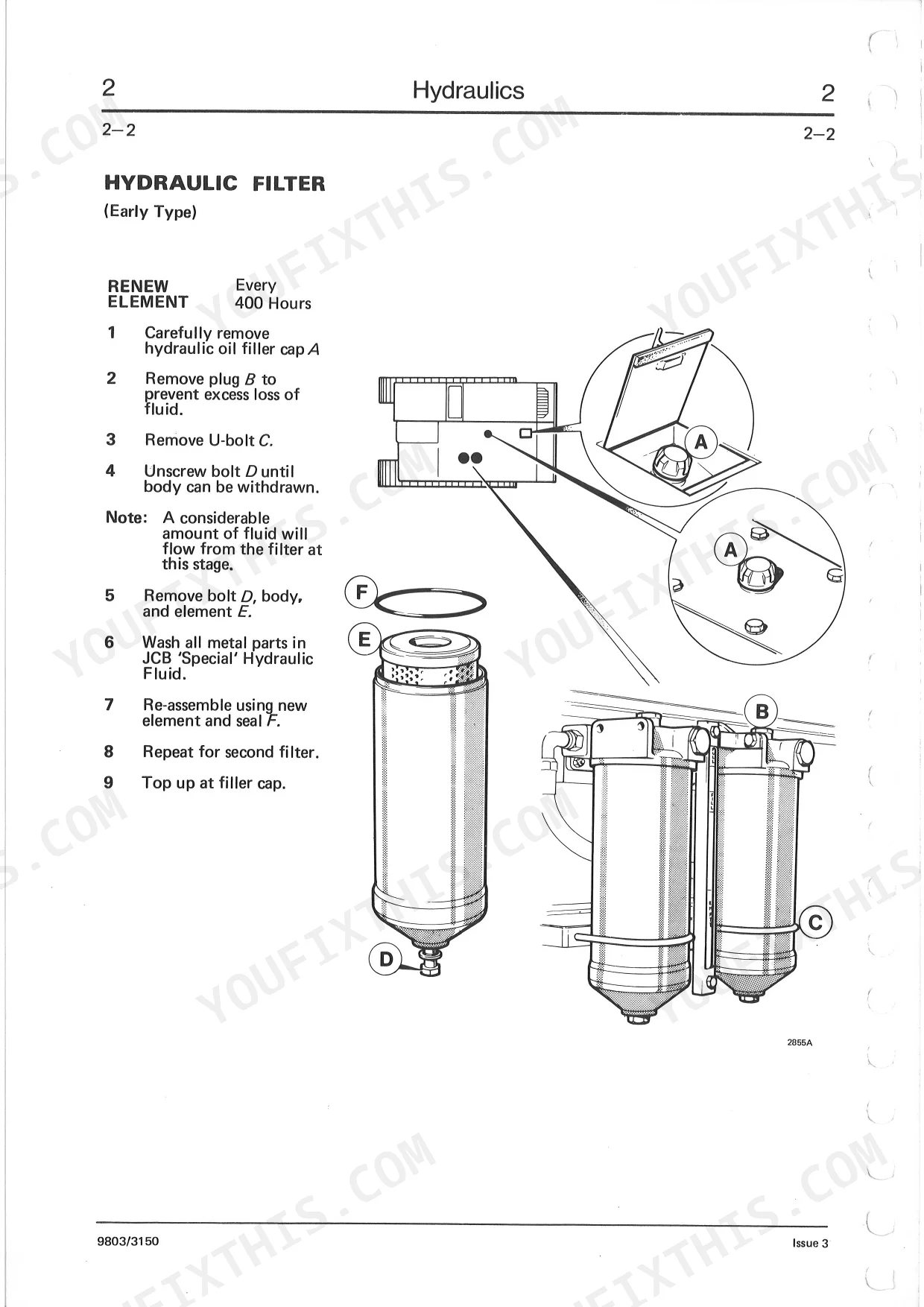
| Hydraulic Filter (Early Type) Replacement Interval | Every 400 Hours | p. 31 |
| Hydraulic Filter (Later Type) Replacement Interval | Every 400 Hours | p. 32 |
| Engine Fuel Filter Replacement Interval | Every 400 Hours | p. 205 |
| Engine Fuel Sediment Bowl Drain Interval | Every 50 Hours | p. 206 |
| Fan Belt Check Tension Interval | 50 Hours | p. 212 |
| Fan Belt Deflection | approximately 10mm (0.4in.) | p. 212 |
| Track Tension | 25mm (1in.) | p. 189 |
| Battery Voltage | 12 volt | p. 217 |
| Battery Capacity | 128 Amp hour | p. 217 |
JCB 805–808 Common Problems This Manual Covers
Engine cranks but will not start
After storage or fuel work these engines often crank without firing because of air in the fuel or an unbled fuel system. The engine section covers the fuel filters, sediment bowl, lift pump, and fuel system service.
Manual Section: Engine p. 201Weak or slow hydraulics
Low oil or clogged filters leave the hydraulics slow and weak, and deeper wear points to the pumps or motors. The hydraulics section covers filter renewal and dismantling the pumps and motors.
Manual Section: Hydraulics p. 24Track tension problems and wear
Track tension is easy to get wrong, leading to premature wear or de-tracking. The track and running gear section covers inspecting, checking, and adjusting the tracks.
Manual Section: Track & Running Gear p. 189Slew gearbox and drive faults
Slew and track gearboxes need the right oil level and can develop faults with neglect. This section covers the track and slew gearboxes and their oil levels.
Manual Section: Gearboxes p. 168Electrical faults and warning lights
Wiring faults and warning lights need the circuit diagrams to trace. The electrical section provides technical data and circuit diagrams for the 805, 806B, 807B, and 808.
Manual Section: Electrics p. 217Slew ring wear or play
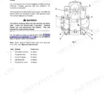
A worn slew ring gives play and rough slewing at the turntable. The body and framework section covers replacing the slew ring and its seal.
Manual Section: Body & Framework p. 156Frequently Asked Questions
Which models and engines are covered?
The manual covers the JCB 805, 805B, 806B, 807B, and 808 excavators. Engines include the Perkins 4.248 and 6.354 range, the turbocharged T6.354, and the 2700 Series units fitted to some machines. It is publication 9803/3150.
How is the manual delivered?
You download the PDF right after purchase, so there is no shipping or wait.
What is the slew ring bolt torque?
The slew ring bolts are torqued to 405 Nm (300 lbf ft). Refitting the slew ring is covered in the Body and Framework section. p. 156
How often should the hydraulic filter be changed?
The hydraulic filter element is renewed every 400 hours. Filter operation and renewal are covered in the Hydraulics section. p. 24
What format is this manual in?
Immediate download of the complete 242-page searchable Service Manual. Access it on any device: laptop at your desk or phone in the field.
Can I print specific sections of this Service Manual?
The PDF is DRM-free, so print whatever sections you need for the shop. Standard letter or A4 paper works.
Are electrical wiring diagrams included in this JCB 805 & variants manual?
Yes, this JCB 805 & variants Service Manual includes complete electrical wiring diagrams, wire routing, and connector pinouts.

Reviews
There are no reviews yet.