


This is the JCB operator's manual for the Loadall telehandlers 506-36, 507-42, 509-42, and 510-56, publication 9811/5967, running 210 pages in English. These machines are powered by the JCB Dieselmax engine, and the manual is the factory operator and maintenance guide meant to stay with the machine.Inside you get the operating instructions, cab controls and instrument panel, boom and carriage controls, load charts, plus a full Routine Maintenance section with service requirements and the fluid, filter, and brake schedules. The Specifications section lists static dimensions and weights, including the 4537 kg maximum lift capacity of the 510-56.Use it to operate the Loadall safely, keep to the service intervals, torque the wheels and ROPS/FOPS mounts, and fit optional attachments through the quick release couplings. It is delivered as an instant PDF download you can read on any device or print.
What's Inside This JCB 506-36, 507-42, 509-42, 510-56 Operator Manual
| System | Pages | Key Topics |
|---|---|---|
| Safety Notices | 9-10 | Important Information, Operator Manual, Safety Warnings |
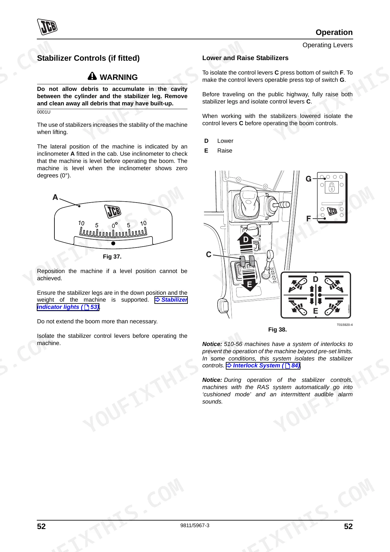
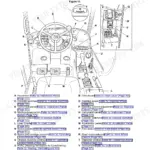
| Operation | 35-102 | Introduction, Before Entering the Cab, Entering and Leaving the Cab (Emergency Exit), Doors and Windows (Opening Closing: Door, Upper Door Section) |
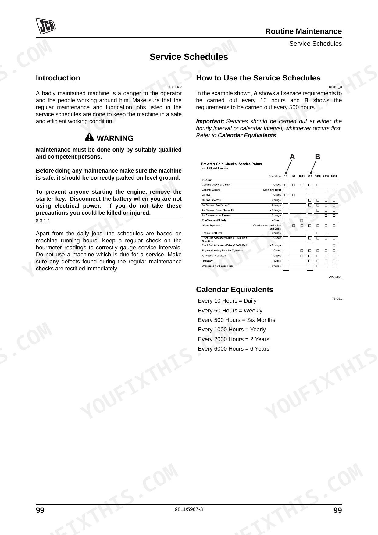
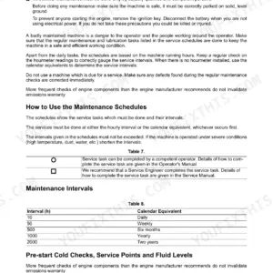
| Service Schedules | 103-114 | Health and Safety, Service Requirements, Introduction, Owner/Operator Support, Service/Maintenance Agreements, Initial Service and Inspection (100 Hours), Fit for Purpose Tests for Lifting Equipment, Obtaining Replacement Parts |
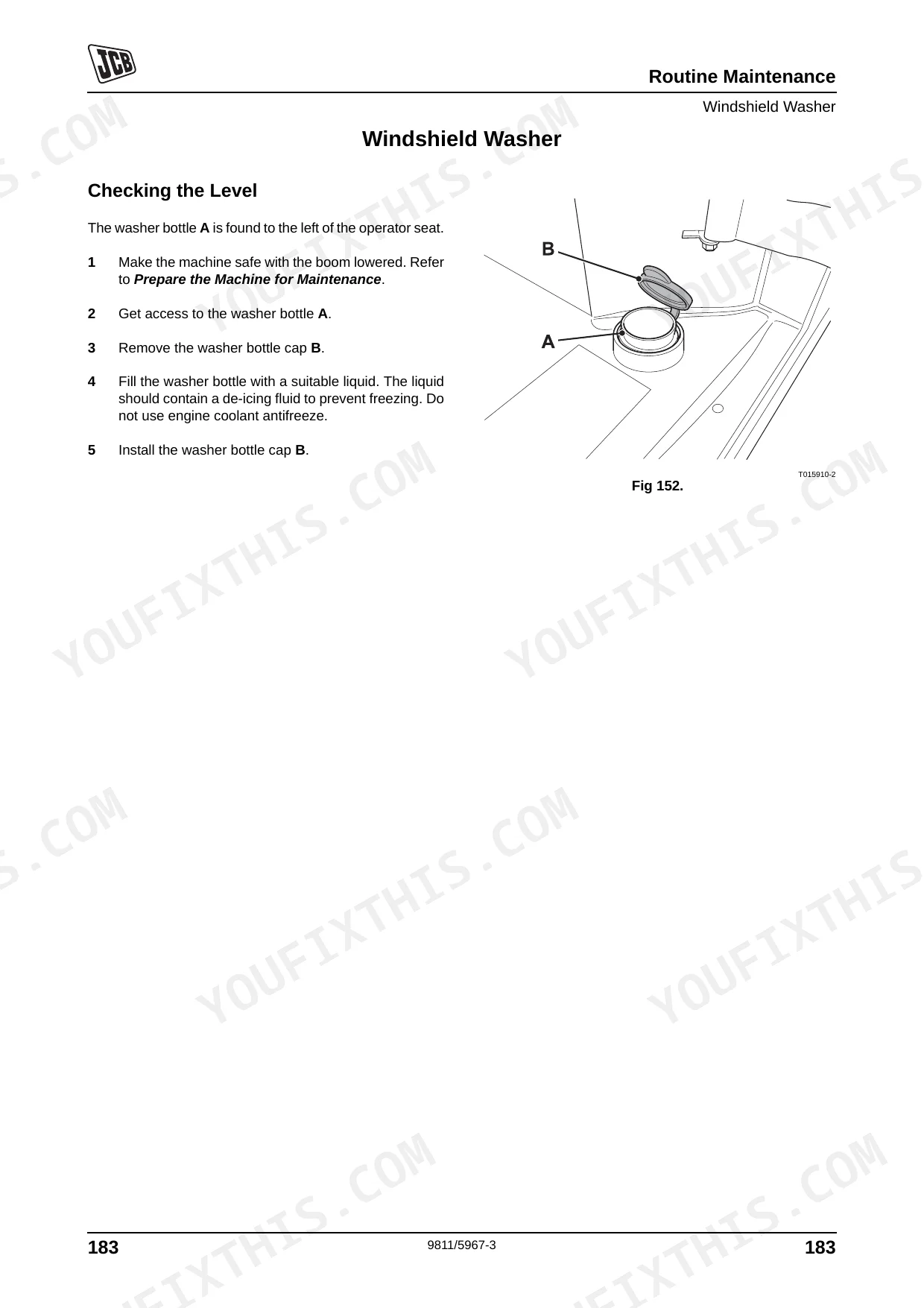
| Prepare the Machine for Maintenance | 115-124 | Fluids, Lubricants and Capacities, Coolant Mixtures, Fuel, Introduction, How to Make the Machine Safe (Boom Lowered) |
| Greasing | 125-137 | Checking for Damage, Cleaning the Machine, Introduction, Preparing the Machine for Cleaning, Check the Machine Body and Structure, Check the Tires, Check the Seat and Seat Belt, Check the Hydraulic Hoses and Fittings |
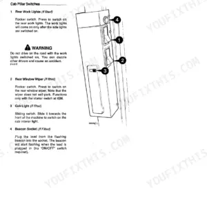
| Access Panels | 138-144 | Oiling, Park Brake Cable, Control Levers, Boom Chains, Battery Cover, Engine Cover, Undershield |
| Electrical System | 145-158 | Boom, Cab Heater and Air Conditioning, Changing the Air Intake Filter, Boom Chains, Brakes, Park Brake, Foot Brake |
| Engine | 159-167 | Oil and Filter, Cooling System, Front End Accessory Drive Belt, Air Filter |
| Hydraulic System | 168-180 | Fuel System, Introduction, Water Separator and Engine Fuel Filter, Bleeding the System, Releasing the Hydraulic Pressure, Oil and Filter, Hose Burst Protection Valves |
| Fire Extinguisher (If Fitted) | 181-194 | Transmission, Gearbox, Axles, Wear Pads, Tires and Wheels, Tire Ballast, Tire Inflation, Wheel Nuts |
| Optional Attachments | 195-198 | Introduction, Attachments for Your Machine, Connecting/Disconnecting Hydraulic Hoses (Introduction, Quick Release Couplings) |
| Warranty Information | 199-202 | Machine Service Record Sheet, Installation Checklist, 1st 100 Hrs./1 Month, 500 Hrs./6 Month, 1000 Hrs./12 Month, 1500 Hrs./18 Month, 2000 Hrs./24 Month, 2500 Hrs./30 Month |
| Specifications | 203-210 | Static Dimensions (All Models, Table 14. Static Dimensions, Table 15. Weight, Fig 161. Static Dimensions) |
Quick Reference Specifications
| Specification | Value | Page |
|---|---|---|
| Air Cleaner Outer Element Replacement Interval | 500 hours | p. 110 |
| Air Cleaner Inner Element Replacement Interval | 1000 hours | p. 110 |
| Engine Fuel Filter Strap Retaining Screw Torque | 24 Nm (17.7 lbf ft) | p. 173 |
| Water Separator Fuel Filter Replacement Interval | 500 hours | p. 110 |
| Hydraulic Oil Filter Replacement Interval | 500 hours | p. 111 |
| Pilot Filter (if fitted) Replacement Interval | 500 hours | p. 111 |
| Engine Oil Filter Replacement Interval | 500 hours | p. 110 |
| Engine Sump Drain Plug Torque | 40-60Nm (30-44lbf ft) | p. 161 |
| All Hoses Condition Check Interval | 50 hours | p. 110 |
| Battery Cover Bolts Torque | 25Nm (17.7 lbf ft) | p. 140 |
| Battery Electrolyte Level | 6 mm (1/4 in) above the plates | p. 153 |
| Park Brake Pad Replacement | Renew both brake pads after emergency use | p. 78 |
JCB 506-36, 507-42, 509-42, 510-56 Common Problems This Manual Covers
Will not crank or charge warning appears
The machine may fail to crank or start intermittently, sometimes with a battery or charging warning lamp. A battery, charging system, or wiring fault in the starter circuit is the usual cause, covered by the electrical checks in this section.
Manual Section: Routine Maintenance p. 103Overheat alarm or power derate
An overheat alarm, derate, or loss of power under load points to low coolant, a blocked radiator, or a fan and thermostat issue. The Routine Maintenance section covers coolant and hose checks, with a 20 litre coolant capacity.
Manual Section: Routine Maintenance p. 103Transmission warning or harsh shifting
Harsh shifting or the machine dropping drive when hot can come from low or contaminated transmission oil or a pressure fault. The Routine Maintenance section covers the transmission oil filter service at its 500 hour interval.
Manual Section: Routine Maintenance p. 103Weak or jerky boom hydraulics
Boom and telehandler functions turn weak, jerky, or slow with low hydraulic oil, clogged filters, or air ingestion. The Routine Maintenance section covers the hydraulic oil filter at a 500 hour interval and the pilot filter cap at 25 Nm.
Manual Section: Routine Maintenance p. 103Water-in-fuel warning after refueling
A water-in-fuel warning or stalling after refueling points to contaminated fuel or an undrained water separator. The Routine Maintenance section covers the fuel filter and water separator element at their 500 hour intervals.
Manual Section: Routine Maintenance p. 103Park brake creeps on hold test
A park brake warning or the machine creeping during the hold test signals brake wear or an adjustment issue. The Routine Maintenance section covers the park brake check interval and the test carried out at about 1500 RPM.
Manual Section: Routine Maintenance p. 103Attachment hoses will not couple
Fitting an attachment means connecting the hydraulic hoses through the quick release couplings correctly. The Optional Attachments section explains the couplings and how to connect and disconnect hoses.
Manual Section: Optional Attachments p. 195Frequently Asked Questions
Which telehandlers does this manual cover?
It covers the JCB Loadall 506-36, 507-42, 509-42, and 510-56 telehandlers with the JCB Dieselmax engine, publication 9811/5967, in 210 pages of English text.
What are the service intervals for the filters?
The Routine Maintenance section gives the outer air cleaner element a 500 hour interval and the inner element 1000 hours, with the fuel, hydraulic, and engine oil filters at 500 hours. p. 103
What is the wheel nut torque?
The Routine Maintenance section gives the front and rear wheel nuts at 680 Nm and the ROPS/FOPS mounting bolts at 205 Nm, with the pilot filter cap at 25 Nm. p. 103
What is the maximum lift capacity?
The Specifications section gives the 510-56 a maximum lift capacity of 4537 kg, along with static dimensions and weights for all four Loadall models. p. 203
How quickly can I access this manual after?
Immediate download of the full 210-page searchable Operator Manual. Open it on any device: a laptop at your desk or a phone in the field.
Can I print specific sections of this manual?
No restrictions at all. Print individual pages, full chapters, or the entire manual. The PDF is completely unlocked.
Reviews
There are no reviews yet.