


Looking for the factory operating guidelines for your compactor? This 99-page JCB Vibromax VM 115 D, VM 115 PD, VM 115 HD, Engine JCB 444, Vibratory Single Drum Roller Operator Manual PDF (OEM #07232/28335) lays out every daily check, control function, and safety protocol. Inside, you get full maintenance schedules, detailed dashboard indicator breakdowns, and proper operating procedures for both smooth and tamping foot drums. You will also find complete wiring diagrams and hydraulic circuit schematics to help track down electrical faults or fluid routing issues right on the job site. Top off the 15-liter crankcase, then verify your wheel nuts are torqued properly between 560 and 600 Nm before starting your shift. A warning light shouldn't stop your crew dead in their tracks. Grab this bookmarked download, open it on your phone right in the cab, and keep the machine moving.
What's Inside This JCB Vibromax VM 115 D & variants Operator Manual
| System | Pages | Key Topics |
|---|---|---|
| Brief Description of the Machine | 6 | Self-Propelled Vibratory Roller, Modular System, Tamping Foot Drum Shells, Hydrostatic Drives, Driving Power Outputs, Vibration Power Outputs |
| Product Identification and Serial Numbers | 7 | Serial Numbers, Product Identification Numbers P.I.N., Model, Drum Drive Gear Box, Steering Unit, Rear Axle |
| Identifying the Machine Parts | 8-9 | Articulation Joint, Smooth Drum, Hydraulic Oil Tank, Diesel Engine, Air Filter, Hydropump Block |
| Basic Safety Notes | 10-19 | Permissible Gradient, Accident Prevention, Electrical Energy, Hydraulic Systems, Noise Insulation, Hot Operating Agents |
| Technical Data | 20-23 | Machine Dimensions, Filling Quantities, Electrical System, Engine, Weights, Vibration System |
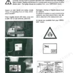
| Decals | 24-25 | Safety Decals, Note Decals, Lifting and Towing Eyes, Battery Voltage, Maintenance Schedule, Hearing Protection |
| Hand Signals | 26-27 | Start Engine Signal, Stop Engine Signal, Drive Forward Signal, Drive Back Signal, Turn Machine Left Signal, Turn Machine Right Signal |
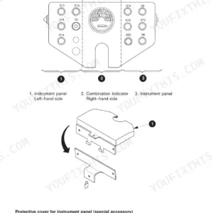
| Operator's Stand | 28-33 | - |
| Operator's Stand and Cab | 34-35 | Cab |
| Special Equipment | 36-37 | Tamping Foot Equipment, Tamping Foot Shells, Levelling Equipment, Heating System, Air Condition, Fan Nozzles |
| ASS-Switch | 38 | Switch Location, Drum Type, Switch Position |
| Instructions for Safe Operation | 39-43 | Before Starting the Engine, Engine Starting Aids, Starting the Engine |
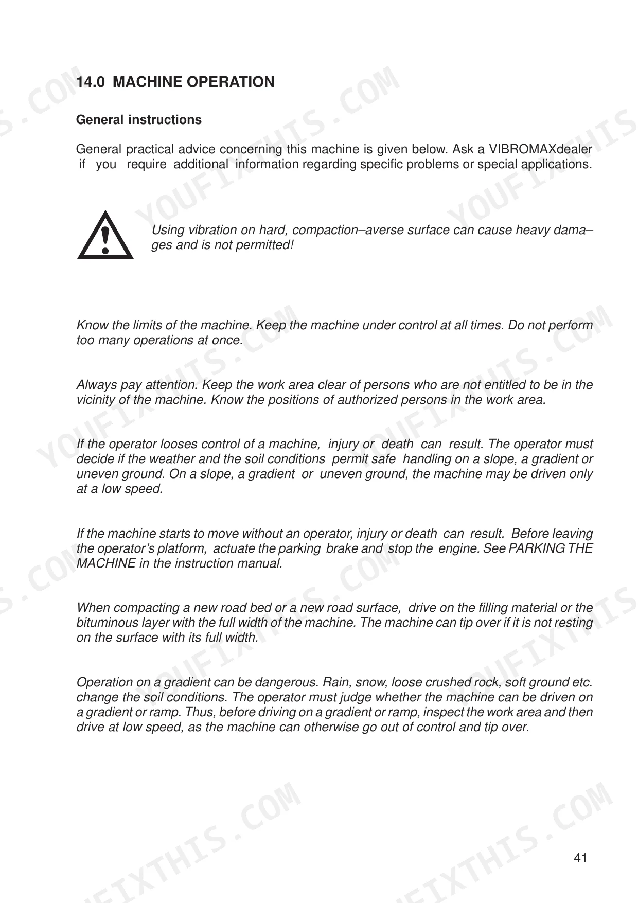
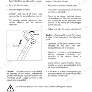
| Machine Operation | 44-46 | Machine Operation Without Vibration, Machine Operation with Vibration |
| Parking the Machine | 47 | Vibration Control, Drive Lever Position, Engine Throttle Control, Parking Brake Switch, Ignition Key, Machine Blocking |
| Towing the Machine | 48 | Tow-Bar Attachment, Transport Mounting Position, Bypass Screw, Multiple Function Valve, Towing Valve Position, Handpump |
| Preparing the Machine for Transport | 49 | Wheel Blocks, Machine Loading, Transport Mounting, Machine Securing, Total Height Measurement, Tyre Air Pressure |
| Before Maintenance/Lubrication | 50-52 | Access |
| Notes for Safe Operation | 53-55 | Diesel Fuel, Fuel Storage, Minimum Requirements for No 2 Diesel Fuel, Fluids and Lubricants |
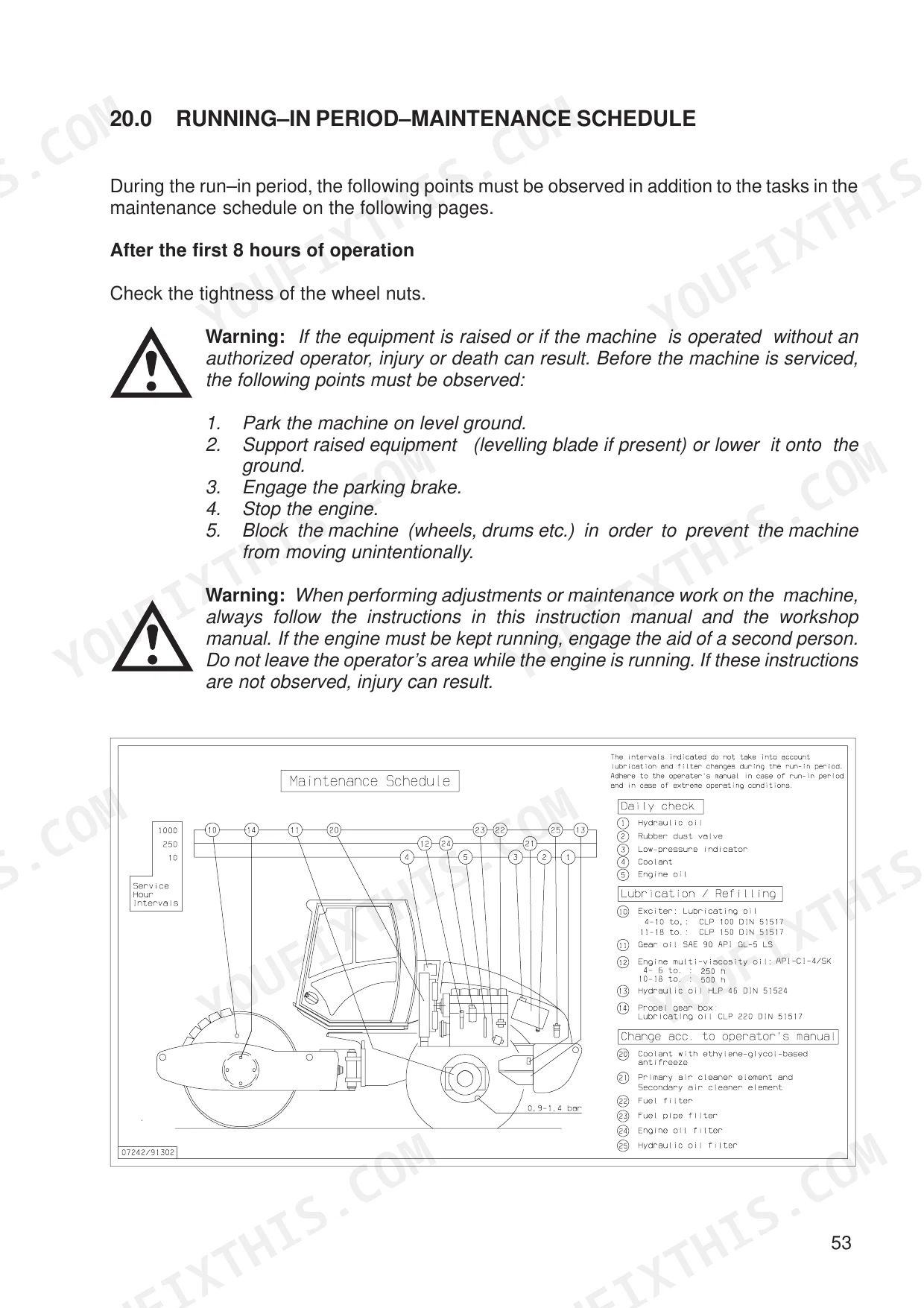
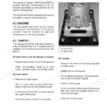
| Running-In Period – Maintenance Schedule | 56-78 | Maintenance Schedule, Grease and Fluid Levels, Engine Lubricating System, Air Filter, Engine Cooling System, Windscreen Washer System, Engine Fuel System, Hydraulic System |
| Hydraulic Circuit Diagram – Measurement Points and Multiple Function Valve | 79-85 | Hydraulic Functional Description, Hydraulic Circuit Diagram, Identifying the Hydraulic Components |
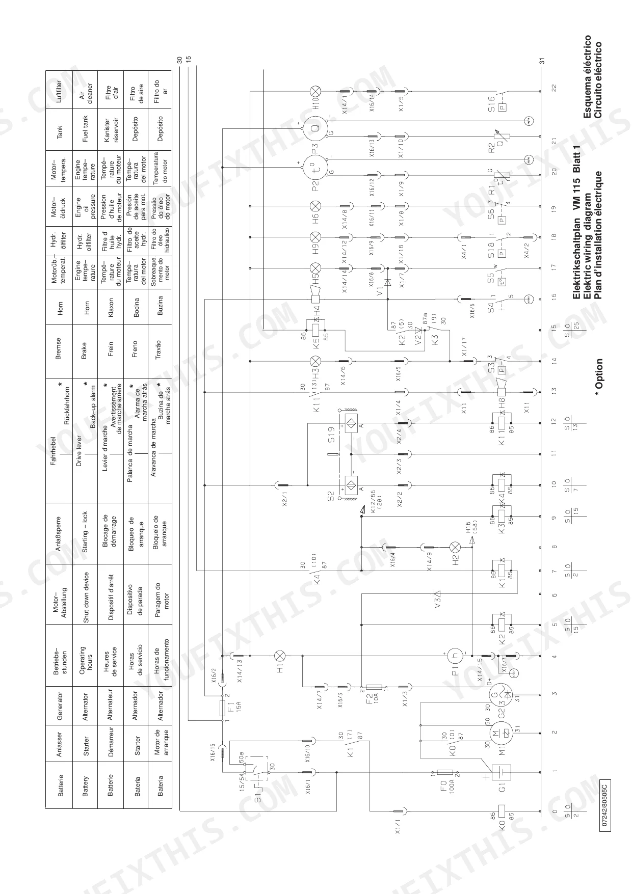
| Electrical System | 86-99 | Battery, Fuses, Relays, Changing Bulbs, Electrical System Circuit Diagram |
Quick Reference Specifications
| Specification | Value | Page |
|---|---|---|
| Wheel nuts tightening torque | 560 to 600 Nm | p. 75 |
| Engine Power | 93 kW (125HP) at 2200 rpm | p. 21 |
| Engine Capacity | 4399 cm³ | p. 21 |
| Fuel Tank Capacity | 300 l | p. 55 |
| Crank Case Oil Capacity | 15 l | p. 55 |
| Hydraulic System Oil Capacity | 80 l | p. 55 |
| Coolant Capacity | 14 l | p. 55 |
| Tyre Pressure | 0,9 to 1,4 bar | p. 21 |
| 1st Vibration Stage Frequency | 1860 rpm (31Hz) | p. 22 |
| 2nd Vibration Stage Frequency | 2160 rpm (36Hz) | p. 22 |
| Inner Turning Radius | 3400 mm | p. 22 |
| Permissible Longitudinal Inclination (gradient) | 30° (58%) | p. 22 |
JCB Vibromax VM 115 D & variants Common Problems This Manual Covers
JCB Vibromax VM 115 hydraulic oil filter warning light illuminated and fluid turning cloudy in the sight glass p. 29
Check the operator controls layout on page 29 to confirm the hydraulic oil filter warning indicator. Inspect the hydraulic oil tank on page 67 for water ingress. Drain and replace the fluid if cloudy, ensuring you refill to the exact 80 l hydraulic system oil capacity specified on page 55.
Manual Section: Hydraulic SystemComplete engine shutdown during operation with no warning lights and high coolant temperature p. 63
Inspect the engine cooling system on page 63 for damaged hoses or leaks. Verify the radiator fluid level when cold. If low, top off the system to the 14 l coolant capacity limit shown on page 55. Check the engine temperature indicator on page 29 to ensure the warning clears before restarting.
Manual Section: Engine Cooling SystemVibratory drum fails to engage or produces intermittent vibration during normal forward travel p. 46
Verify the vibration control switch on page 30 is engaged and the engine is running at full throttle as described on page 45. Check the technical specifications on page 22 to ensure the 1st vibration stage frequency reaches 1860 rpm (31Hz). Inspect the hydraulic fluid level on page 67 if vibration remains weak.
Manual Section: Machine OperationDriving vibration feels excessive and wheel nuts appear loose after replacing a deflated rear tyre p. 75
Check the tyre pressure and inflate to between 0,9 to 1,4 bar as required. Tighten all lug nuts using a calibrated wrench to the exact 560 to 600 Nm wheel nuts tightening torque specified on page 75. Verify tire condition before operating on steep grades.
Manual Section: Running-In Period – Maintenance ScheduleFrequently Asked Questions
What does the hydraulic warning light mean on a VM 115 HD?
The hydraulic oil filter warning light indicates that the hydraulic oil filter element is clogged. If this light comes on, the filter element needs attention.
Where is the diagnostic connector on a JCB VM 115 D/PD/HD?
The diagnostic connector, referred to as the "Diagnose jack," is located on the console. It is identified as item 2 under the "Gear shift switch - * Traction control" section.
How do you fix jcb Vibromax VM 115 hydraulic oil filter warning light illuminated and fluid turning cloudy in the sight glass?
Check the operator controls layout on page 29 to confirm the hydraulic oil filter warning indicator. Inspect the hydraulic oil tank on page 67 for water ingress. Drain and replace the fluid if cloudy, ensuring you refill to the exact 80 l hydraulic system oil capacity specified on page 55.
How do you fix complete engine shutdown during operation with no warning lights and high coolant temperature?
Inspect the engine cooling system on page 63 for damaged hoses or leaks. Verify the radiator fluid level when cold. If low, top off the system to the 14 l coolant capacity limit shown on page 55. Check the engine temperature indicator on page 29 to ensure the warning clears before restarting.
How will I receive this JCB Vibromax VM 115 D & variants Operator Manual?
Instant PDF download. You get the full 99-page searchable Operator Manual immediately after payment. Open it on your laptop, tablet, or phone right in the shop.
Are there any print restrictions on this JCB Vibromax VM 115 D & variants?
Absolutely. No DRM or copy protection. Print the whole manual or just the pages you need. Any home or office printer works.
Are there hydraulic schematics in this JCB Vibromax VM 115 D & variants manual?
Included. A hydraulic system diagram shows the main hydraulic layout for the JCB Vibromax VM 115 D & variants.

Reviews
There are no reviews yet.