


Need the exact operating procedures and daily maintenance intervals for your vibratory single drum roller? This 96-page JCB Vibromax VM 46 D, VM 46 PD, VM 46D, VM 46PD operator manual PDF (OEM #07211/28435A) covers the complete cab controls, hydrostatic drives, and vibration systems for the VM 46 series. Open to a complete maintenance schedule detailing everything from engine cooling system checks to rear axle fluid levels. You get full hydraulic circuit diagrams, electrical system schematics, and proper transport mounting instructions to keep your crew safe. Swap out the 07222/50253 hydraulic oil filter every 1000 hours or annually to protect the hydrostatic drives. Don't risk machine downtime over a missed service interval. Download this bookmarked file, pull it up on your tablet right in the operator's seat, and get to work.
What's Inside This JCB Vibromax VM 46 D & variants Operator Manual
| System | Pages | Key Topics |
|---|---|---|
| Brief Description of the Machine | 6 | Smooth Drum Shells, Tamping Foot Drum Shells, Modular System, Cab, Hydrostatic Drives, ROPS |
| Product Identification and Serial Numbers | 7 | Serial Numbers, Model, Drum Drive Gear Box, Steering Unit, Rear Axle, Vibration Motor |
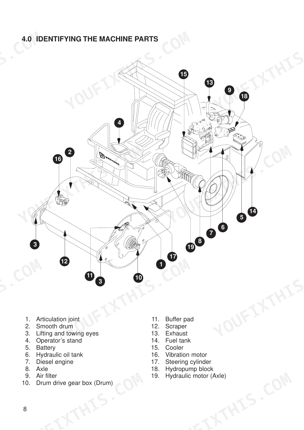
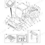
| Identifying the Machine Parts | 8-9 | Articulation Joint, Smooth Drum, Lifting and Towing Eyes, Operator's Stand, Battery, Hydraulic Oil Tank |
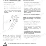
| Basic Safety Notes | 10-19 | Warning Notes, Safety Symbols, Permissible Gradient, Electrical Energy, Hydraulic Systems, Transport and Towing |
| Technical Data | 20-22 | Machine Dimensions, Filling Quantities, Electrical System, Engine, Weights, Speed |
| Decals | 23-25 | Safety Decals, Note Decals, Lifting and Towing Eyes Decal, Battery Voltage Decal, Operator's Seat Warning Decal, Maintenance Schedule Decal |
| Hand Signals | 26-27 | Start the Engine, Stop the Engine, Drive Forward, Drive Back, Turn the Machine Left, Turn the Machine Right |
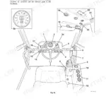
| Operator's Stand | 28-33 | - |
| Special Equipment | 34-37 | Tamping Foot Equipment, Tamping Foot Shells, Levelling Equipment, Compaction Measurement Device, Vibrator Frequency, Display Brightness |
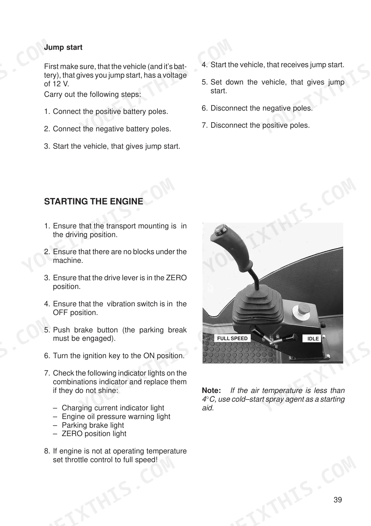
| Instructions for Safe Operation | 38-42 | Before Starting the Engine, Engine Starting Aids, Starting the Engine |
| Machine Operation | 43-45 | Machine Operation Without Vibration, Machine Operation with Vibration |
| Parking the Machine | 46 | Vibration, Drive Lever, Engine Throttle Control, Parking Brake Switch, Ignition Key, Brakes |
| Towing the Machine | 47 | Towing Vehicle, Tow-Bar, Transport Mounting, Bypass Screw, Multiple Function Valve, Towing Valve |
| Preparing the Machine for Transport | 48 | Transport Vehicle, Wheels, Blocks, Ramp, Parking Brake Switch, Transport Mounting |
| Before Maintenance/Lubrication | 49-51 | Access |
| Notes for Safe Operation | 52-54 | Diesel Fuel, Fuel Storage, Minimum Requirements for No 2 Diesel Fuel, Fluids and Lubricants |
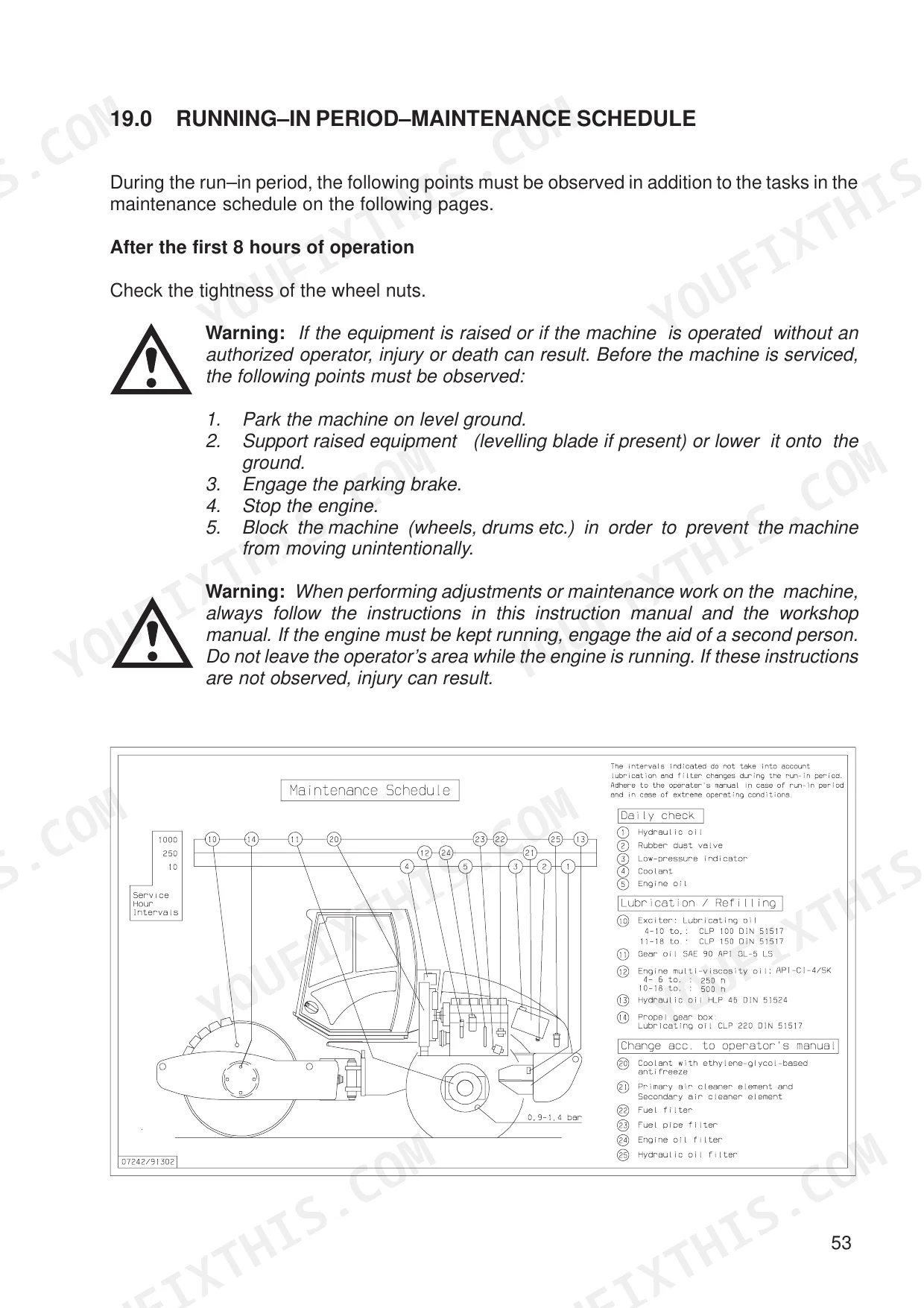
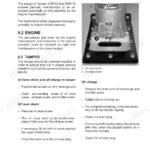
| Running-In Period – Maintenance Schedule | 55-75 | Maintenance Schedule, Grease and Fluid Levels, Engine Lubricating System, Air Filter, Engine Cooling System, Engine Fuel System, Venting the Fuel System for Injection Pumps |
| Storing the Machine | 76-77 | Hydraulic System Controls, Fuel Tank, Engine Oil, Oil Filter, Air Filter, Battery |
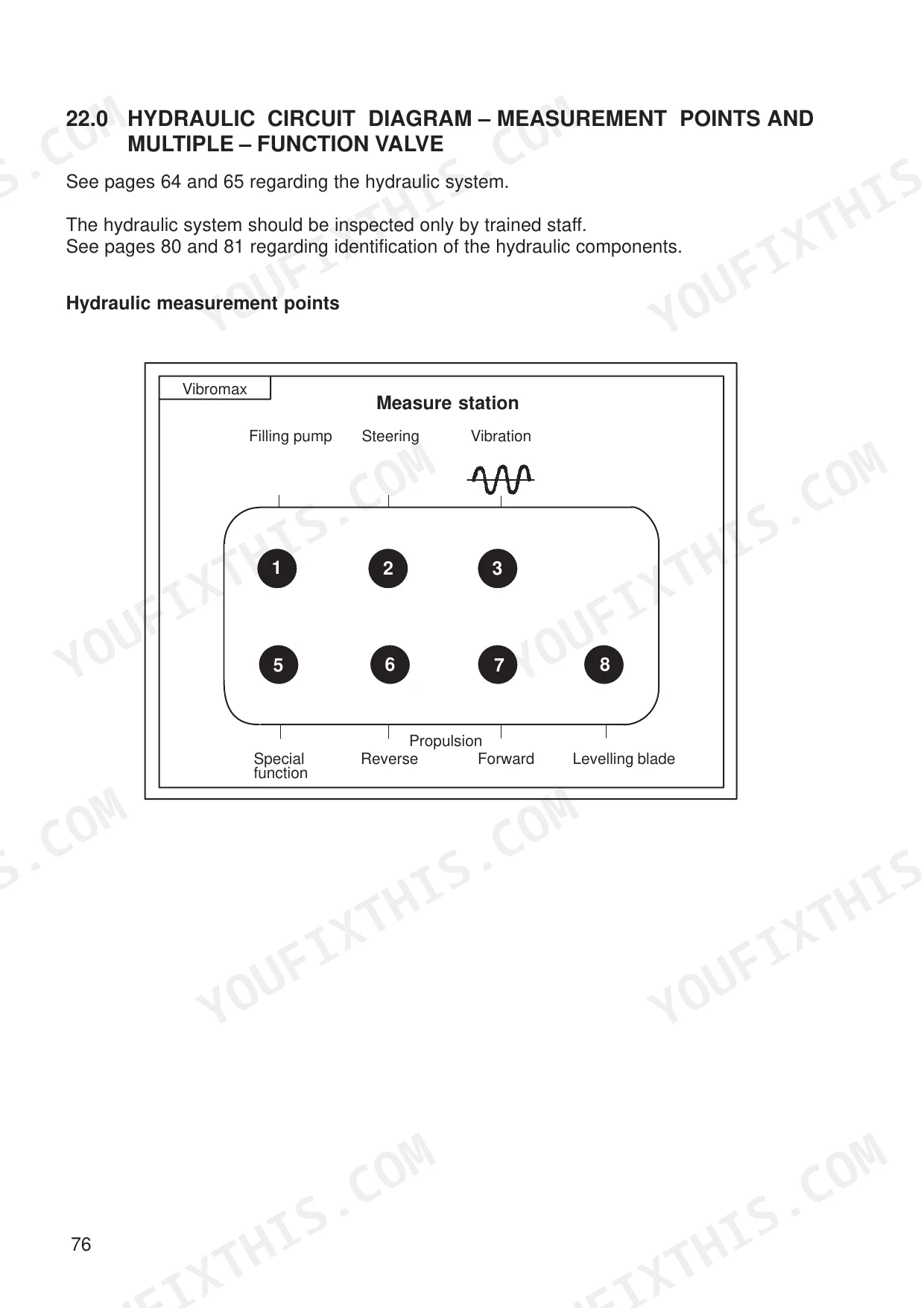
| Hydraulic Circuit Diagram – Measurement Points and Multiple Function Valve | 78-84 | Hydraulic Functional Description, Hydraulic Circuit Diagram, Identifying the Hydraulic Components |
| Electrical System | 85-96 | Battery, Fuses, Relays, Changing Bulbs, Electrical System Circuit Diagram |
Quick Reference Specifications
| Specification | Value | Page |
|---|---|---|
| Bleed screw (fuel system) | 8 Nm | p. 65 |
| Rear axle filler plug | 150 Nm | p. 68 |
| Troubleshooting steps | Not specified as a step-by-step guide; general advice to inspect, repair leaks, and consult trained staff is provided. | p. 18 |
| Hydraulic oil filter part number | 07222/50253 | p. 58 |
| Hydraulic oil filter replacement interval | Every 1000 hours or annually | p. 67 |
| Engine oil filter part number | 07211/50720 | p. 58 |
| Engine oil filter replacement interval | Every 250 hours of operation | p. 60 |
| Fuel line filter part number | 02611/00046 | p. 58 |
| Fuel filter part number | 07211/50730 | p. 58 |
| Drive belts inspection interval | Every 10 hours of operation or daily | p. 73 |
| Generator belt tension check interval | Every 250 hours or monthly | p. 56 |
| Vibration system oil capacity | 2.5 l | p. 54 |
JCB Vibromax VM 46 D & variants Common Problems This Manual Covers
JCB Vibromax VM 46D hydraulic oil filter warning light illuminates on dashboard and vibration will not engage p. 28
Inspect the hydraulic oil filter warning light meaning on page 28. Replace the filter element with part number 07222/50253 if the light stays on. Tighten the new filter 1/2 to 3/4 turn by hand. Perform this replacement every 1000 hours or annually.
Manual Section: Engine Indicator Lights & Horn DiagnosticsEngine cranks continuously but refuses to start after running the fuel tank completely dry p. 65
Fill the 180 l fuel tank with clean diesel. Vent the fuel system for the injection pumps as detailed on page 65. Loosen the fuel system bleed screw to release trapped air, then tighten it exactly to 8 Nm before attempting to restart the engine.
Manual Section: Fuel System BleedingDashboard indicators remain completely dark when turning the ignition key to the start position p. 86
Verify the F0 main fuse condition located in the electrical distribution box on page 86. Replace the blown 100A main fuse with a new one. Check the battery fluid level, which must be inspected every 250 hours of operation to maintain proper charging.
Manual Section: Electrical System Fuse ReplacementRoller pulls heavily to one side during forward travel or feels unstable on flat ground p. 74
Check the tyre pressure on page 21. Inflate the tyres to the specified 0,9 to 1,4 bar. Inspect the wheel nuts on page 74 and torque them between 366 and 413 Nm to ensure the wheels are securely mounted to the drive axles.
Manual Section: Wheel & Tyre InspectionEngine temperature warning light flashes continuously and coolant temperature gauge reads unusually high during normal operation p. 73
Inspect the engine drive belts for proper condition and tension as shown on page 73. Perform this drive belt inspection every 10 hours of operation or daily. Check the generator belt tension every 250 hours or monthly according to the maintenance schedule on page 56.
Manual Section: Drive Belt InspectionFrequently Asked Questions
What do the warning lights mean on a JCB Vibromax VM 46 D?
The machine uses indicator lights to signal issues. The charging current indicator light illuminates for charging circuit faults, while the engine oil pressure warning light indicates low engine oil pressure. The engine temperature warning light comes on, and the horn sounds, if the fan belt fails or the engine temperature exceeds the safe operating range. Additionally, the hydraulic oil filter warning light indicates a clogged filter element, and the air filter warning light signals a clogged air filter element.
What are the replacement specifications for Hydraulic filters?
The hydraulic oil filter, part number 02611/00046, should be changed every 1000 hours of operation or annually, or whenever the hydraulic oil filter warning light illuminates. To replace, clean the area around the filter, loosen the union nut, remove the filter bowl and element, clean the bowl, check the O-ring, then install the new element and bowl and tighten the union nut.
How do you fix jcb Vibromax VM 46D hydraulic oil filter warning light illuminates on dashboard and vibration will not engage?
Inspect the hydraulic oil filter warning light meaning on page 28. Replace the filter element with part number 07222/50253 if the light stays on. Tighten the new filter 1/2 to 3/4 turn by hand. Perform this replacement every 1000 hours or annually.
How do you fix engine cranks continuously but refuses to start after running the fuel tank completely dry?
Fill the 180 l fuel tank with clean diesel. Vent the fuel system for the injection pumps as detailed on page 65. Loosen the fuel system bleed screw to release trapped air, then tighten it exactly to 8 Nm before attempting to restart the engine.
What format is this manual in?
A 96-page Operator Manual in searchable PDF format, available the moment you complete checkout. View on computer, tablet, or phone, with no shipping wait.
Can I print this manual?
Yes. The PDF has no DRM restrictions, so print any page or section you need for your shop. Works with any standard printer.
Does this JCB Vibromax VM 46 D & variants manual include hydraulic schematics?
Yes, this JCB Vibromax VM 46 D & variants Operator Manual includes a hydraulic system diagram.
Reviews
There are no reviews yet.