


Keeping your compactor out of the shop and on the jobsite starts with this 115-page JCB Vibromax W 1105 D, W 1105 PD, Vibratory Single Drum Roller Operator Manual PDF (OEM #07241/28035C). Open it up to find detailed daily operating procedures, complete fluid capacities, and step-by-step maintenance schedules tailored to your exact machine. You get high-quality hydraulic circuit diagrams with multiple measurement points to help diagnose drive issues, clear dashboard indicator guides, and complete electrical system wiring diagrams to track down any lighting or sensor fault. Tighten the scraper fastening nuts to the frame at 366-390 Nm, lock down your heavy wheel nuts between 560 and 600 Nm, and confirm the operator's stand rubber buffers are torqued to 210 Nm before rolling over rough terrain. Downtime burns through your profit margins. Download this bookmarked file right now, pull it up on your smartphone or tablet, and keep your equipment moving.
What's Inside This JCB Vibromax W 1105 D, W 1105 PD, Vibratory Single Drum Roller Operator Manual
| System | Pages | Key Topics |
|---|---|---|
| Brief Description of the Machine | 6 | The Terms "Right", "Left", "Front" and "Rear", Self-Propelled Vibratory Roller, Large Selection of Equipment, Hydrostatic Drives, Self-Propelled Roller Components |
| Product Identification and Serial Numbers | 7 | Serial Numbers (Product Identification Numbers P.I.N.), Model, Drum Drive Gear Box, Serial Number, Steering Unit, Rear Axle |
| Identifying the Machine Parts | 8-9 | Articulation Joint, Smooth Drum, Lifting Eye, Operator's Stand, Battery, Hydraulic Oil Tank |
| Basic Safety Notes | 10-18 | Warning Notes and Symbols, Basics; Use As Intended, Organizational Measures, Selection of Staff and Staff Qualifications; Basic Duties |
| Technical Data | 20-23 | Machine Dimensions, Filling Quantities, Electrical System, Engine, Weights, Speed |
| Decals | 24-25 | Note Decals and Safety Decals, Illegible Decals, Clean Illegible Decals, Decals Below Instrument Panel, Decals on Lifting and Towing Eyes, Decals for Transport Mounting |
| Hand Signals | 26-27 | Start the Engine, Stop the Engine, Drive Forward, Drive Back, Stop, Turn the Machine Left |
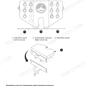
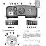
| Instrument Panel | 28-32 | Left-Hand Side, Vibration Switches, Gear Shift Switch, Lighting System Switch, Automatic Vibration Switch, Right-Hand Side |
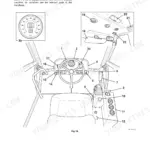
| Driving/Steering Equipment and Emergency Off-Switch | 33-34 | Operating Console, Backup Alarm, Emergency – Switch, Drive Lever, Vibration Switch, Steering Wheel |
| Operator's Seat | 35 | Angle Adjustment of Back-Rest, Weight Adjustment, Arm Rest Adjustment, Hand Wheel for Lumbar Support, Angle Adjustment of Seat, Height Adjustment |
| Operator's Stand and Cab | 36-38 | Keys, Hydraulically Operated Engine Hood, Cab |
| Special Equipment | 39-40 | Tamping Foot – Equipment, Levelling Equipment, Tamping Foot – Shells, ASS-Switch |
| Instructions for Safe Operation | 41-45 | Before Starting the Engine, Engine Starting Aids, Starting the Engine, Engine Speed |
| Machine Operation | 46-47 | Machine Operation Without Vibration, Machine Operation with Vibration |
| Parking the Machine | 48 | Stopping the Machine |
| Towing the Machine | 49-50 | Tow-Bar, Transport Mounting, Bypass Screw, Towing Valve, Handpump |
| Preparing the Machine for Transport | 51 | Blocks, Transport Vehicle, Doors and Motor Hood, Total Height, Tyre Air Pressure |
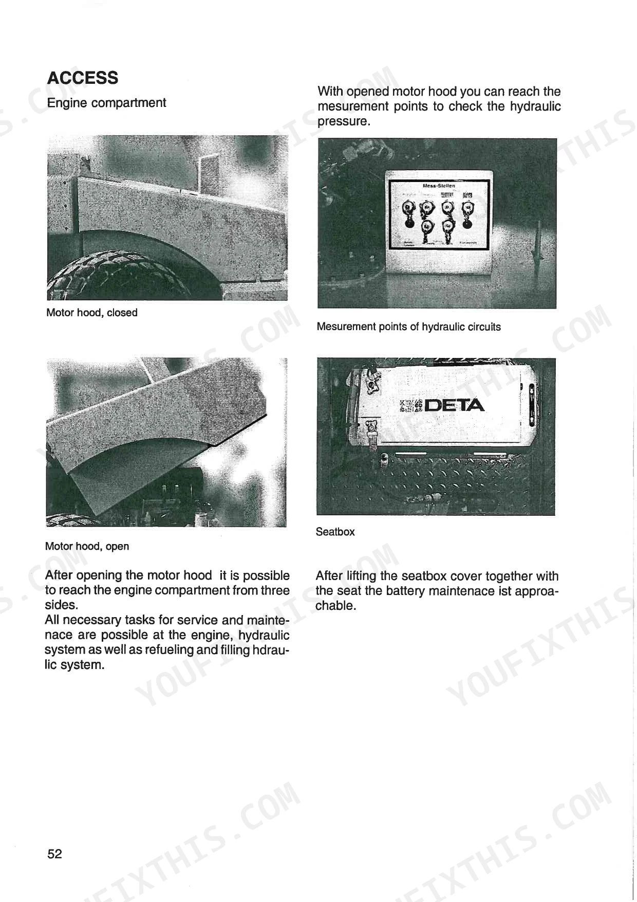
| Before Maintenance/Lubrication | 52-54 | Access |
| Notes for Safe Operation | 55-57 | Diesel Fuel, Fuel Storage, Minimum Requirements for No 2 Diesel Fuel, Fluids and Lubricants |
| Running-In Period/Maintenance Schedule | 58-81 | Maintenance Schedule, Grease and Fluid Levels, Engine Lubricating System, Air Filter, Engine Cooling System, Engine Fuel System, Venting the Fuel System for Injection Pumps |
| Operator's Stand | 82-83 | ROPS – Roll-Over Protection Structure |
| Storing the Machine | 84-85 | Machine Cleaning, Hydraulic System, Fuel Tank, Fuel Filter, Engine Oil, Battery |
| Hydraulic Circuit Diagram – Measurement Points and Multiple Function Valve | 86-93 | Hydraulic Functional Description, Hydraulic Circuit Diagram, Identifying the Hydraulic Components |
| Electrical System | 94-115 | Battery, Fuses, Relays, Changing Bulbs, Electrical System Circuit Diagram |
Quick Reference Specifications
| Specification | Value | Page |
|---|---|---|
| Scraper fastening torque (8 screws) | 185 to 197 Nm | p. 74 |
| Scraper fastening torque (nuts to frame) | 366 to 390 Nm | p. 74 |
| Wheel nuts tightening torque | 560 to 600 Nm | p. 79 |
| Operator's stand rubber buffer tightening torque (a) | 210 Nm | p. 80 |
| Hydraulic system measurement points (diagnostic aid) | 1-8 measurement points | p. 84 |
| Hydraulic oil filter replacement interval | every 1000 hours of operation or annually | p. 69 |
| Hydraulic oil filter part number | 02611/00046 | p. 59 |
| Fuel filter replacement interval | every 500 hours of operation or annually | p. 67 |
| Fuel filter part number | 04900/10017 | p. 59 |
| Primary air filter replacement criteria | after it has been cleaned six times or more than two years old | p. 62 |
| Secondary air filter replacement criteria | if primary filter cleaned third time, more than two years old, or damaged | p. 62 |
| Drive belt tension value (Cummins belt tension gauge) | 80 to 100 lbs | p. 78 |
JCB Vibromax W 1105 D, W 1105 PD, Vibratory Single Drum Roller Common Problems This Manual Covers
JCB Vibromax W 1105 D single drum roller drive response is weak and vibration does not engage p. 59
Inspect the hydraulic oil level and verify the system contains the required 80 l capacity as specified on page 55. Check the hydraulic oil filter and replace it every 1000 hours of operation or annually using part number 02611/00046 found on page 59.
Manual Section: Running-In Period/Maintenance ScheduleEngine starts poorly, stalls under heavy load, or loses power completely during regular compaction operations p. 67
Drain the water separator and check the fuel tank, which has a 390 l capacity. Replace the fuel filter every 500 hours of operation or annually as directed on page 67. Bleed the fuel system to remove trapped air before attempting to restart the engine.
Manual Section: Running-In Period/Maintenance ScheduleDashboard warning light flashes continuously and engine struggles to maintain RPM in dry, dusty conditions p. 63
Remove the primary air filter element and blow it out from the inside out. Limit compressed air pressure to not greater than 2.1 bar according to the instructions on page 63. Replace the element entirely after it has been cleaned six times or is more than two years old.
Manual Section: Running-In Period/Maintenance ScheduleExcessive cab vibration and rattling noises coming from the operator platform during normal rolling operation p. 80
Inspect the rubber buffers on the operator's stand for tears or damage. Torque the mounting hardware (a) to exactly 210 Nm as specified on page 80. Replace any damaged isolator mounts immediately to prevent structural damage to the platform assembly.
Manual Section: Running-In Period/Maintenance ScheduleFrequently Asked Questions
What are the torque specs for the JCB Vibromax W 1105 D wheel/drum bolts?
For the wheels, tighten the wheel nuts in the sequence given in the manual to 560 to 600 Nm. For the drum, the Vulcollan scrapers are fastened with 8 screws, requiring a tightening torque of 185 to 197 Nm. The tamping foot scraper also requires a tightening torque of 185 to 197 Nm for each nut or screw.
How do you fix JCB Vibromax W 1105 D single drum roller drive response is weak and vibration does not engage?
Inspect the hydraulic oil level and verify the system contains the required 80 l capacity as specified on page 55. Check the hydraulic oil filter and replace it every 1000 hours of operation or annually using part number 02611/00046 found on page 59.
How do you fix engine starts poorly, stalls under heavy load, or loses power completely during regular compaction operations?
Drain the water separator and check the fuel tank, which has a 390 l capacity. Replace the fuel filter every 500 hours of operation or annually as directed on page 67. Bleed the fuel system to remove trapped air before attempting to restart the engine.
How do you fix dashboard warning light flashes continuously and engine struggles to maintain RPM in dry, dusty conditions?
Remove the primary air filter element and blow it out from the inside out. Limit compressed air pressure to not greater than 2.1 bar according to the instructions on page 63. Replace the element entirely after it has been cleaned six times or is more than two years old.
What format is this JCB Vibromax W 1105 D, W 1105 PD, Vibratory Single Drum?
Immediate download of the complete 115-page searchable Operator Manual. Access it on any device, from a laptop at your desk to a phone in the field.
Are hydraulic system diagrams in this JCB Vibromax W 1105 D, W 1105 PD?
Yes, this JCB Vibromax W 1105 D, W 1105 PD, Vibratory Single Drum Roller Operator Manual includes a hydraulic system diagram.
Reviews
There are no reviews yet.