


All 780 pages of this John Deere 310G Technical Manual (OEM #TM1886) are built for one machine: the 310G Backhoe Loader, from the MFWD powered axle and power shift transmission down to the loader bucket and backhoe attachment. You get step-by-step service procedures, exploded-view diagrams across axles, steering, brakes, and both working ends, plus system diagrams covering every hydraulic circuit on your machine. Electrical system coverage spans the alternator and charging circuit, harness routing, instruments, and motor actuators. Snug the rear wheel-to-axle cap screws to 495 ± 99 N•m (365 ± 73 lb-ft) and torque the control valve hydraulic hose fittings to exactly 50 N•m (37 lb-ft). Done guessing at numbers you can't verify. Bookmarked by section — tap the chapter, find the spec, get back to work.
What's Inside This John Deere 310G Manual
| System | Pages | Key Topics |
|---|---|---|
| General Information | 9-28 | Safety Information |
| Wheels | 29-38 | Powered or Non-Powered Wheels and Fastenings |
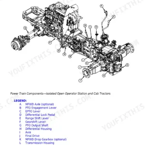
| Axles and Suspension Systems | 39-138 | Input Drive Shafts and U-Joints, Non-Powered Wheel Axles, Powered Wheel Axle, Axle Shaft, Bearings and Reduction Gears |
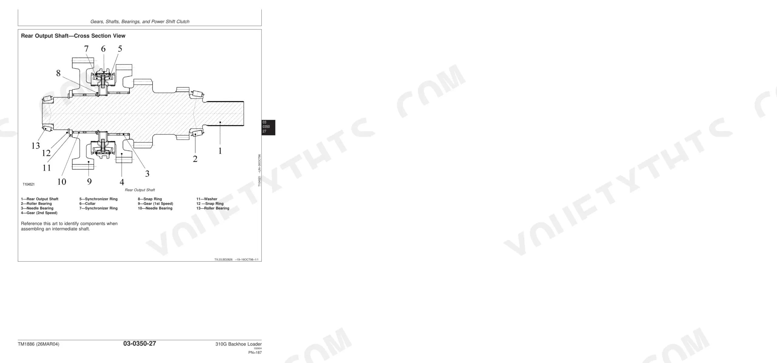
| Transmission | 139-234 | Removal and Installation, Controls Linkage, Input Drive Shafts and U-Joint, Gears, Shafts, Bearings, And Power Shift Clutch, Hydraulic System |
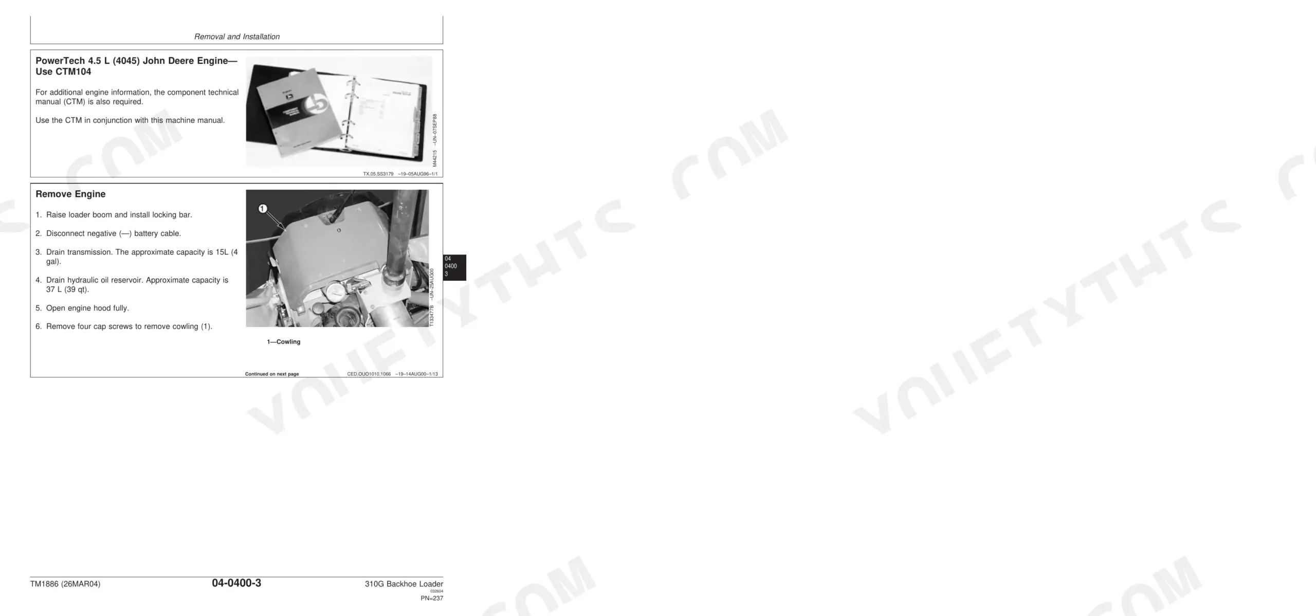
| Engine | 235-256 | Removal and Installation |
| Engine Auxiliary Systems | 257-290 | Cold Weather Starting Aid, Cooling System, Speed Controls, Intake System, Exhaust System, External Fuel Supply System |
| Torque Converter | 291-294 | Turbine, Gears and Shaft |
| Steering System | 295-340 | Steering Cylinder, Steering Column, Standard & Tilt Steering Wheel, Steering Valve, Non-Powered Axle Steering Cylinder |
| Service Brakes | 341-364 | Active Elements, Hydraulic System |
| Electrical Systems | 365-400 | Batteries, Support, And Cables, Alternator, Regulator and Charging System Wiring, Wiring Harness and Switches, Instruments and Indicators, Motors and Actuators |
| Frames, Chassis or Supporting Structure | 401-410 | Frame Installation, Chassis Weights |
| Operator's Station | 411-512 | Removal and Installation, Operator Enclosure, Seat and Seat Belt, Heating and Air Conditioning |
| Sheet Metal and Styling | 513-526 | Hood and Engine Enclosure, Miscellaneous Shields, Grille and Grille Housing, Fenders |
| Safety, Convenience and Miscellaneous | 527-536 | Radio, Horn and Warning Devices |
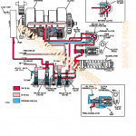
| Main Hydraulic System | 537-560 | Hydraulic Pump, Hydraulic Filter, Reservoir, Hydraulic and Transmission Oil Coolers |
| Loader | 561-654 | Bucket, Control Linkages, Hydraulic System |
| Backhoe | 655-764 | Bucket, Control Linkage, Frames, Hydraulic System |
| Dealer Fabricated Tool | 765-780 | DFT1146 Axle Mounting Bracket, DFT1147 Axle Rolling Torque Bar, DFT1143 Transmission Support Bracket, DFT1163 MFWD Snap Ring Removal and Installation Tool |
Quick Reference Specifications
| Specification | Value | Page |
|---|---|---|
| Rear Wheel-to-Axle Cap Screw Torque | 495 ± 99 N•m (365 ± 73 lb-ft) | p. 31 |
| Control Valve Hydraulic Hoses Torque | 50 N•m (37 lb-ft) | p. 540 |
| Battery Post Nuts Torque | 9.2 N•m (82 lb-in.) | p. 367 |
| Alternator Pulley Torque | 70 N•m (52 lb-ft) | p. 379 |
| Support-to-Air Cleaner Cap Screws—Torque | 20 N•m (15 lb-ft) | p. 276 |
| Rear Wheel Weight (with fluid) | 420 kg (930 lb) | p. 31 |
| Drive Shaft Cap Screws Torque | 41 N•m (30 lb-ft) | p. 41 |
| Axle Pivot Pin Cap Screw Torque | 215 N•m (158 lb-ft) | p. 54 |
| Service Brake Disk Thickness | 5 mm (0.197 in.) Minimum | p. 68 |
| Pinion Shaft Nut Torque | 600 N•m (442 lb-ft) | p. 68 |
| Ring Gear Backlash | 0.15—0.25 mm (0.006—0.010 in.) | p. 68 |
| Transmission Weight | 227 kg (500 lb) Approximate | p. 141 |
John Deere 310G Common Problems This Manual Covers
John Deere 310G transmission won't release brakes or machine refuses to shift into gear
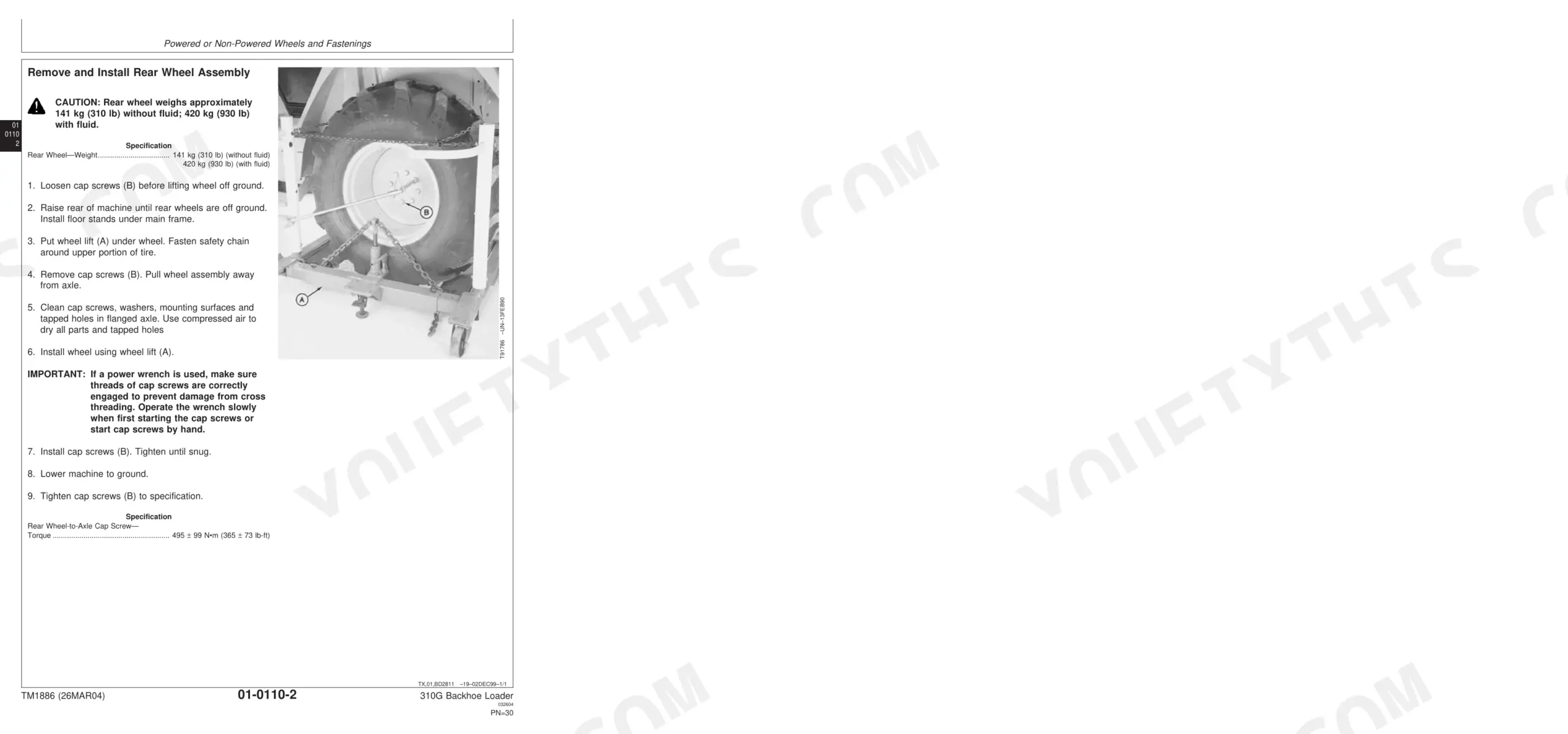
Check hydraulic supply pump pressure before pulling the transmission. Review the circuit diagram to trace the fault upstream. If brakes still drag after pressure is restored, remove the brake disks from the axle assembly and measure thickness; minimum is 5 mm (0.197 in.) per page 68. Discard any disk that measures below spec.
Manual Section: TransmissionHydraulic system responds slowly or won't move at all, boom and bucket dead p. 537
Inspect hydraulic fluid level and check the de-stroke valve for sticking or debris. Torque any loose control valve hose fittings to 50 N•m (37 lb-ft) as specified on page 540. If fluid is full and fittings are tight but output stays weak, trace the circuit from the pump forward and remove the pump for inspection per page 537.
Manual Section: Main Hydraulic SystemHydraulic oil leaking from high-pressure hoses or fittings, puddle forming under machine p. 540
Identify the leak source with the engine running at low idle. Clean the area, then watch for spray or seepage at each fitting and hose junction. Tighten loose fittings to 50 N•m (37 lb-ft) per page 540. Replace any hose showing cracks, abrasion, or swelling at the ferrule. Recheck all connections after 30 minutes of operation.
Manual Section: Main Hydraulic SystemEngine won't crank or turns over slowly, no electrical response when key is turned p. 365
Test battery voltage under load before replacing the starter. Clean and re-torque both post nuts to 9.2 N•m (82 lb-in.) per page 367. Check ground resistance from battery negative to block and frame; a corroded ground here regularly kills starters and relays. Work through the wiring harness and starter relay tests in the Electrical Systems procedures starting at page 365.
Manual Section: Electrical SystemsEngine hard to start, loses power under load, excessive black smoke from exhaust p. 257
Replace the fuel filter and air filter before chasing injection faults. Clean the air cleaner housing and torque the support cap screws to 20 N•m (15 lb-ft) per page 276. Check for intake restrictions at the pre-cleaner and main element. Work through intake, exhaust, and fuel supply checks in the Engine Auxiliary Systems section starting at page 257.
Manual Section: Engine Auxiliary SystemsFrequently Asked Questions
Why won't the John Deere 310G transmission release the brakes or shift into gear?
Check hydraulic supply pump pressure before disassembling the transmission. If brakes still drag after pressure is restored, remove the brake disks from the axle assembly and measure thickness — minimum is 5 mm (0.197 in.) per page 68. Discard any disk below spec and confirm hydraulic circuit continuity before reassembly.
The 310G hydraulic system responds slowly or the boom and bucket are completely dead — where do I start?
Inspect hydraulic fluid level and check the de-stroke valve for sticking or debris. Torque any loose control valve hose fittings to 50 N•m (37 lb-ft) per page 540. If output stays weak with fluid full and fittings tight, trace the circuit from the pump forward and pull the pump for inspection per page 537.
What are the torque specs for John Deere 310G wheel nuts?
The torque specifications for the John Deere 310G wheel nuts vary by type. Rear wheel-to-axle cap screws require a torque of 495 ± 99 N•m (365 ± 73 lb-ft). For front wheels, the hub nut (with MFWD) should be torqued to 300 + 100 — 40 N•m (221 + 73 — 29 lb-ft), while the cap screw (without MFWD) requires 136 + 20 — 68 N•m (100 + 15 — 50 lb-ft).
How quickly can I access this manual after buying?
Immediate download of the complete 780-page searchable Technical Manual. Access it on any device — laptop at your desk or phone in the field.
Can I print this manual?
Absolutely. No DRM or copy protection. Print the whole manual or just the pages you need. Any home or office printer works.
Document Quality
This is a native digital PDF document, allowing you to search and copy the full text content. The text quality is crisp and consistently easy to read throughout. Diagrams and illustrations are a mix of clear raster images and sharp vector graphics, with all labels being readable. Pages are clean with no scan artifacts, stains, or skewed content. However, there are numerous blank or filler pages, primarily serving as section separators or content placeholders, which you will encounter while navigating.

Reviews
There are no reviews yet.