


All 370 pages of this John Deere 318D repair manual PDF (OEM #TM11399) zero in on one thing: getting your 318D, 319D, 320D, or 323D Skid Steer Loader back to factory spec. Inside: exploded views covering tracks, axles, hydrostatic motors, and loader components, plus unified inch and metric torque tables so you're never guessing at a fastener. You get detailed step-by-step procedures spanning the hydrostatic pump, park brake, transmission controls, hydraulic system components, cooling package, and full boom and cylinder assembly. Snug the fan drive motor inlet and outlet hydraulic hoses to 63 N·m (46.5 lb.-ft.) and the oil filter manifold cap screws to 18.5 N·m (164 lb.-in.); both numbers pulled straight from factory tables, not a forum post. Your machine is down. Grab the PDF on any device, jump to any section with pre-built bookmarks, and start wrenching.
What's Inside This John Deere 318D, 319D, 320D, 323D Repair Manual
| System | Pages | Key Topics |
|---|---|---|
| General Information | 5-34 | Safety (Recognize Safety Information, Follow Safety Instructions, Operate Only If Qualified, Wear Protective Clothing, Avoid Unauthorized Machine Modifications, Inspect Machine, Stay Clear of Moving Parts, Avoid High-Pressure Fluids, Avoid High-Pressure Oils, Work in Ventilated Area, Prevent Fires, Prevent Battery Explosions, Handle Chemical Products Safely, Dispose of Waste Properly, Prepare for Emergencies, Clean Debris From Machine, Use Steps and Handholds Correctly, Start Only From Operator's Seat, Use and Maintain Seat Belt, Prevent Unintended Machine Movement, Avoid Work Site Hazards, Keep Riders Off Machine, Avoid Backover Accidents, Avoid Machine Tip Over, Operating on Slopes, Operating or Traveling on Public Roads, Inspect and Maintain ROPS, Add and Operate Attachments Safely, Park and Prepare for Service Safely, Service Cooling System Safely, Remove Paint Before Welding or Heating, Make Welding Repairs Safely, Drive Metal Pins Safely, Service Tires Safely, Handle Cab Door Safely) |
| Wheels or Tracks | 35-58 | Powered Wheels and Fastenings (Wheel Remove and Install, Tire Remove and Install) |
| Axles and Suspension Systems | 59-66 | Drive Axle Housing and Support (Remove and Install, Disassemble and Assemble), Axle Shaft, Bearings |
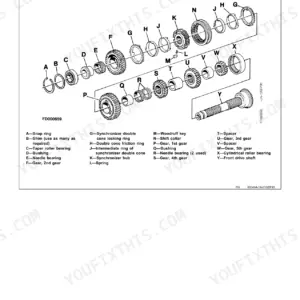
| Transmission | 67-188 | Group 0315, Controls Linkage (Centering Plate Remove and Install, Centering Plate Inspection, Steering Dampener Remove and Install, Steering Dampener Inspection, Control Lever Remove and Install, Control Lever Disassemble and Assemble, Steering Cross Shaft Assembly Remove and Install, Steering Cross Shaft Disassemble and Assemble, Control Lever Handle Remove and Install) |
| Engine | 189-196 | Removal and Installation (PowerTech E 2.4L and 3.0L Diesel Engines, Engine Remove and Install), PowerTech E 2.4L and 3.0L Diesel Engines, Engine Remove and Install |
| Engine Auxiliary System | 197-212 | Group 0510, Cooling Systems (Fan Remove and Install, Charge Air Cooler Remove and Install, Radiator Remove and Install, Cooling Package Remove and Install, Thermostat and Diffuser/Flow Divider Remove and Install) |
| Frame or Supporting Structure | 213-218 | Frame Installation (Welding on Machine, Welding Repair of Major Structure, Counterweight Remove and Install, Raising and Blocking Machine), Welding on Machine |
| Operator's Station | 219-256 | Group 1800, Removal and Installation (Operator's Station Remove and Install) |
| Sheet Metal and Styling | 257-262 | Hood or Engine Enclosure (Footwell Remove and Install, Side Panel Remove and Install, Engine Cover Remove and Install), Footwell Remove and Install |
| Safety and Convenience | 263-266 | Radio (Antenna Remove and Install), Radio Antenna Remove and Install |
| Main Hydraulic System | 267-292 | Hydraulic System (Hydraulic/Hydrostatic Component Failure Cleanup Procedure, Fan Drive Motor Remove and Install, Fan Bypass Valve Remove and Install, Hydraulic Oil Cooler Remove and Install, Hydraulic Oil Reservoir Remove and Install, Hydraulic Pump Remove and Install, Hydraulic Pump Disassemble and Assemble, High Flow Hydraulic Pump Remove and Install, High Flow Valve Remove and Install, High Flow Valve Disassemble and Assemble) |
| Loader | 293-346 | Group 3104, Attachment Coupler (Quik-Tatch™: Coupler Remove and Install, Actuator Remove and Install) |
| Dealer Fabricated Tools | 347-370 | DFT1101 Boom Lifting Bracket, DFT1323 Engine Lifting Bracket, ST4920 Track Recoil Spring Disassembly and Assembly Tool |
Quick Reference Specifications
| Specification | Value | Page |
|---|---|---|
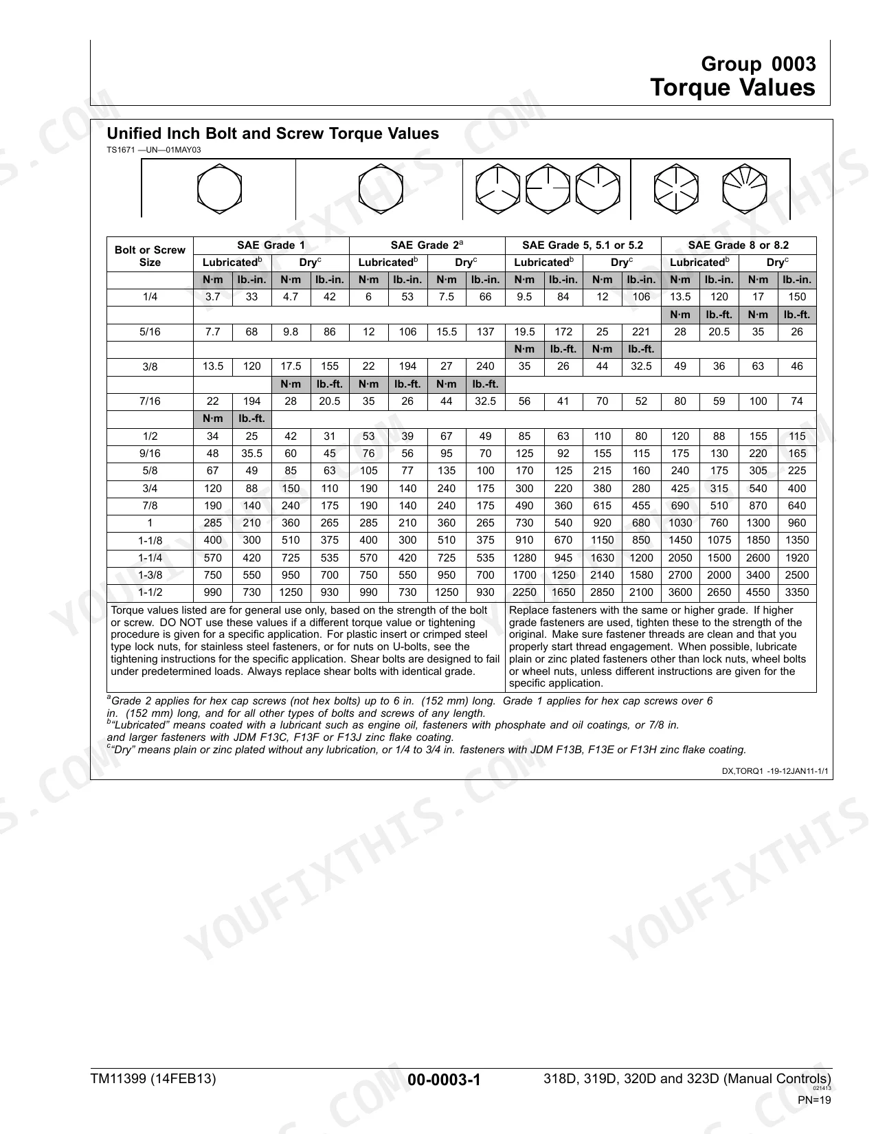
| Unified Inch Bolt and Screw Torque Values | See table on page 19 | p. 19 |
| Metric Bolt and Screw Torque Values | See table on page 20 | p. 20 |
| Hydraulic Oil Filter Manifold Cap Screw—Torque | 18.5 N·m (164 lb.-in.) | p. 346 |
| Fan Drive Motor Inlet and Outlet Hydraulic Hoses—Torque | 63 N·m (46.5 lb.-ft.) | p. 275 |
| Fan Drive Motor Case Drain Hydraulic Hose—Torque | 37 N·m (27 lb.-ft.) | p. 275 |
| Electric Quik-Tatch™ Coupler—Weight | 79 kg (174 lb.) | p. 296 |
| Boom-To-Coupler Pin Cap Screw—Torque | 320 N·m (236 lb-ft) | p. 297 |
| Hydraulic Oil Filter Restriction Switch—Torque | 4.0 N·m (36 lb.-in.) | p. 346 |
| 1/4 inch bolt, SAE Grade 5, Dry Torque | 12 lb-in | p. 19 |
| M6 bolt, Class 8.8, Dry Torque | 11.3 lb-in | p. 20 |
| M8 T-Bolt Torque | 21 lb-ft | p. 21 |
| Wheel Retainer Nuts Torque | 175 lb-ft | p. 37 |
John Deere 318D, 319D, 320D, 323D Common Problems This Manual Covers
John Deere 318D quick-tach linkage binds up and will not lock or release attachment p. 297
Inspect the actuator and pins for wear or debris. Clean the latch assembly thoroughly. Replace damaged components and tighten the boom-to-coupler pin cap screw to 320 N·m (236 lb-ft) as specified on page 297. Test the electric coupler for smooth operation.
Manual Section: LoaderLoader arms slowly drop when parked or hydraulic system feels weak under load p. 346
Check the hydraulic oil filter manifold for leaks or bypass conditions. Drain the reservoir and replace the restricted filter element. Torque the hydraulic oil filter manifold cap screw to 18.5 N·m (164 lb.-in.) using the values found on page 346. Bleed the cylinders.
Manual Section: Main Hydraulic SystemEngine overheats during normal heavy work cycles and fan drive motor leaks hydraulic fluid p. 275
Verify the cooling package is free of debris. Inspect the fan drive motor for external leaks. Replace the damaged hydraulic lines and tighten the inlet and outlet hoses to 63 N·m (46.5 lb.-ft.) as shown on page 275. Refill the system.
Manual Section: Main Hydraulic SystemMachine feels sluggish while turning and drive axle exhibits excessive rolling drag p. 64
Remove the wheel and inspect the axle housing support. Verify the axle bearing rolling drag torque is between 40 and 120 lb-in as detailed on page 64. Fill the axle housing with exactly 8 oz of oil. Reinstall the wheel retainer nuts.
Manual Section: Axles and Suspension SystemsFrequently Asked Questions
Why do the loader arms on my 318D slowly drift down when parked?
Check the hydraulic oil filter manifold for leaks or bypass conditions. Replace a restricted filter element and torque the manifold cap screw to 18.5 N·m (164 lb.-in.) per the factory spec on page 346. Then bleed the lift cylinders to restore full pressure.
My 318D quick-tach will not lock or release the attachment — what should I check?
Inspect the actuator and latch pins for wear or debris and clean the assembly thoroughly. Tighten the boom-to-coupler pin cap screw to 320 N·m (236 lb-ft) as specified on page 297, then test the electric coupler for smooth engagement.
The fan drive motor on my 320D is leaking hydraulic fluid — what is the correct hose torque?
Replace any damaged hoses and tighten the fan drive motor inlet and outlet hoses to 63 N·m (46.5 lb.-ft.) and the case drain hose to 37 N·m (27 lb.-ft.), both from the factory table on page 275. Refill and check the cooling package for debris.
Where do I find torque specs for fasteners on my 318D or 323D?
Pages 19 and 20 contain the unified inch and metric bolt torque tables covering all standard fastener grades used on the machine. Look up the fastener size and grade before reassembly to avoid over- or under-torquing.
My 318D drive axle has excessive rolling drag — what is the correct axle bearing spec?
Remove the wheel and verify axle bearing rolling drag torque is between 40 and 120 lb-in as detailed on page 64. Fill the axle housing with exactly 8 oz of oil before reinstalling the wheel retainer nuts.
Document Quality
This document is a native digital PDF, allowing you to search and copy all text. The text is consistently crisp and very easy to read throughout. Diagrams and illustrations are sharp vector graphics, ensuring all labels and details remain clear at any zoom level. Pages are clean, free of scan artifacts or marks, and maintain a consistent, professional layout. You will find several blank filler pages, which is typical for this type of technical manual.


Reviews
There are no reviews yet.