

Part of the John Deere Repair Manuals.
This is the John Deere 318D, 319D, 320D, and 323D Skid Steer Loader Repair Manual (Manual Controls), factory publication TM11399. It covers machines built with the PowerTech E 2.4L and 3.0L diesel engines, across serial numbers up to 192141 and 192142 and after. The 370 page manual is the technician-level repair volume, organized by John Deere's standard section and group structure.
Inside you get removal, installation, disassembly, and assembly procedures for the wheels and tracks, drive axles, transmission and controls linkage, engine, cooling package, operator's station, main hydraulic system, and the loader attachment coupler. Torque values, wear tolerances, and dealer-fabricated tool references are included so you can complete repairs to factory specification.
Delivered as an instant PDF download, it is fully searchable and prints cleanly for shop use. Independent mechanics, owners, and restorers can diagnose and repair these loaders without paying dealer labor rates.
What's Inside This John Deere 318D, 319D, 320D, 323D Repair Manual
| System | Pages | Key Topics |
|---|---|---|
| General Information | 5-34 | Safety (Recognize Safety Information, Follow Safety Instructions, Operate Only If Qualified, Wear Protective Clothing, Avoid Unauthorized Machine Modifications, Inspect Machine, Stay Clear of Moving Parts, Avoid High-Pressure Fluids, Avoid High-Pressure Oils, Work in Ventilated Area, Prevent Fires, Prevent Battery Explosions, Handle Chemical Products Safely, Dispose of Waste Properly, Prepare for Emergencies, Clean Debris From Machine, Use Steps and Handholds Correctly, Start Only From Operator's Seat, Use and Maintain Seat Belt, Prevent Unintended Machine Movement, Avoid Work Site Hazards, Keep Riders Off Machine, Avoid Backover Accidents, Avoid Machine Tip Over, Operating on Slopes, Operating or Traveling on Public Roads, Inspect and Maintain ROPS, Add and Operate Attachments Safely, Park and Prepare for Service Safely, Service Cooling System Safely, Remove Paint Before Welding or Heating, Make Welding Repairs Safely, Drive Metal Pins Safely, Service Tires Safely, Handle Cab Door Safely) |
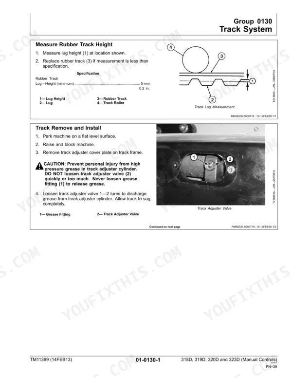
| Wheels or Tracks | 35-58 | Powered Wheels and Fastenings (Wheel Remove and Install, Tire Remove and Install) |
| Axles and Suspension Systems | 59-66 | Drive Axle Housing and Support (Remove and Install, Disassemble and Assemble), Axle Shaft, Bearings |
| Transmission | 67-188 | Group 0315, Controls Linkage (Centering Plate Remove and Install, Centering Plate Inspection, Steering Dampener Remove and Install, Steering Dampener Inspection, Control Lever Remove and Install, Control Lever Disassemble and Assemble, Steering Cross Shaft Assembly Remove and Install, Steering Cross Shaft Disassemble and Assemble, Control Lever Handle Remove and Install) |
| Engine | 189-196 | Removal and Installation (PowerTech E 2.4L and 3.0L Diesel Engines, Engine Remove and Install), PowerTech E 2.4L and 3.0L Diesel Engines, Engine Remove and Install |
| Engine Auxiliary System | 197-212 | Group 0510, Cooling Systems (Fan Remove and Install, Charge Air Cooler Remove and Install, Radiator Remove and Install, Cooling Package Remove and Install, Thermostat and Diffuser/Flow Divider Remove and Install) |
| Frame or Supporting Structure | 213-218 | Frame Installation (Welding on Machine, Welding Repair of Major Structure, Counterweight Remove and Install, Raising and Blocking Machine), Welding on Machine |
| Operator's Station | 219-256 | Group 1800, Removal and Installation (Operator's Station Remove and Install) |
| Sheet Metal and Styling | 257-262 | Hood or Engine Enclosure (Footwell Remove and Install, Side Panel Remove and Install, Engine Cover Remove and Install), Footwell Remove and Install |
| Safety and Convenience | 263-266 | Radio (Antenna Remove and Install), Radio Antenna Remove and Install |
| Main Hydraulic System | 267-292 | Hydraulic System (Hydraulic/Hydrostatic Component Failure Cleanup Procedure, Fan Drive Motor Remove and Install, Fan Bypass Valve Remove and Install, Hydraulic Oil Cooler Remove and Install, Hydraulic Oil Reservoir Remove and Install, Hydraulic Pump Remove and Install, Hydraulic Pump Disassemble and Assemble, High Flow Hydraulic Pump Remove and Install, High Flow Valve Remove and Install, High Flow Valve Disassemble and Assemble) |
| Loader | 293-346 | Group 3104, Attachment Coupler (Quik-Tatch™: Coupler Remove and Install, Actuator Remove and Install) |
| Dealer Fabricated Tools | 347-370 | DFT1101 Boom Lifting Bracket, DFT1323 Engine Lifting Bracket, ST4920 Track Recoil Spring Disassembly and Assembly Tool |
Documents This Manual Refers To
The manufacturer cites these publications by number. We carry them:
Quick Reference Specifications
| Specification | Value | Page |
|---|---|---|
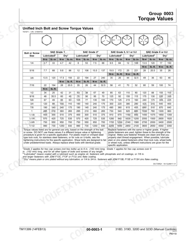
| Unified Inch Bolt and Screw Torque Values | See table on page 19 | p. 19 |
| Metric Bolt and Screw Torque Values | See table on page 20 | p. 20 |
| Hydraulic Oil Filter Manifold Cap Screw—Torque | 18.5 N·m (164 lb.-in.) | p. 346 |
| Fan Drive Motor Inlet and Outlet Hydraulic Hoses—Torque | 63 N·m (46.5 lb.-ft.) | p. 275 |
| Fan Drive Motor Case Drain Hydraulic Hose—Torque | 37 N·m (27 lb.-ft.) | p. 275 |
| Electric Quik-Tatch™ Coupler—Weight | 79 kg (174 lb.) | p. 296 |
| Boom-To-Coupler Pin Cap Screw—Torque | 320 N·m (236 lb-ft) | p. 297 |
| Hydraulic Oil Filter Restriction Switch—Torque | 4.0 N·m (36 lb.-in.) | p. 346 |
| 1/4 inch bolt, SAE Grade 5, Dry Torque | 12 lb-in | p. 19 |
| M6 bolt, Class 8.8, Dry Torque | 11.3 lb-in | p. 20 |
| M8 T-Bolt Torque | 21 lb-ft | p. 21 |
| Wheel Retainer Nuts Torque | 175 lb-ft | p. 37 |