
Part of the John Deere Repair Manuals.
Need factory-level rebuild procedures for your John Deere JD450? This John Deere jd450 service manual pdf spans 572 pages and covers both Crawler Tractor and Crawler Loader configurations, from engine separation and tune-up through transmission rebuilds, steering clutches, winch systems, and the full loader boom. You get wiring diagrams for the alternator charging circuit and ignition system, hydraulic schematics covering the 15 GPM and 30 GPM pump setups, a full troubleshooting section, torque tables, and page after page of exploded views across every major assembly. Torque the cylinder head bolts to 110 ft-lbs in the factory sequence, then confirm your alternator is outputting 14.4 volts at 75°F. No more guessing at specs or chasing forum answers. Download it now, search any term by keyword, and jump straight to any section with built-in bookmarks.
What's Inside This John Deere JD450 Manual
| System | Pages | Key Topics |
|---|---|---|
| Introduction | 4-6 | Safety Precautions, Model Overview, Serial Number Location, Tractor Identification |
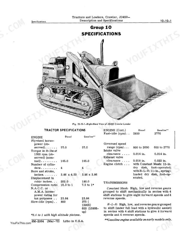
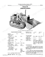
| Description and Specifications | 7-14 | Engine Models (Gasoline and Diesel), Dimensions, Weight, Track Specifications, Hydraulic Capacity, Performance Ratings |
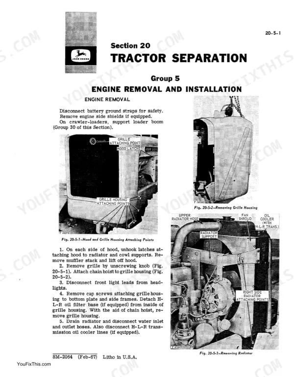
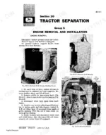
| Tractor Separation | 15-36 | Engine Removal and Installation, Clutch Housing Removal and Installation, Final Drive Removal and Installation, Steering Clutch Removal and Installation |
| Periodic Lubrication | 37-42 | Lubrication Timetable |
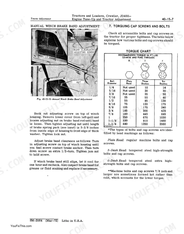
| Engine Tune-Up and Tractor Adjustment | 43-72 | Purpose of Tune-Up and Adjustment, Engine Tune-Up, Tractor Adjustment, Loader Adjustment |
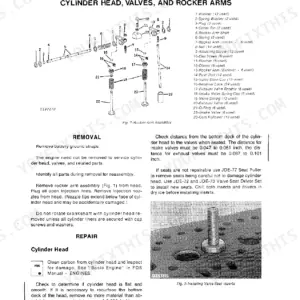
| Basic Engine | 73-118 | Cylinder Head, Valves, And Related Parts, Cylinder Block, Cylinder Lines, Pistons, And Connecting Rods |
| Engine Lubrication System | 119-126 | Oil Pump and Filter |
| Governor and Speed Control Linkage | 127-134 | Governor, Speed Control Linkage |
| Engine Cooling System | 135-144 | Description and Servicing, Radiator, PRessure Cap, And Fan Assembly, Water Pump and Thermostat |
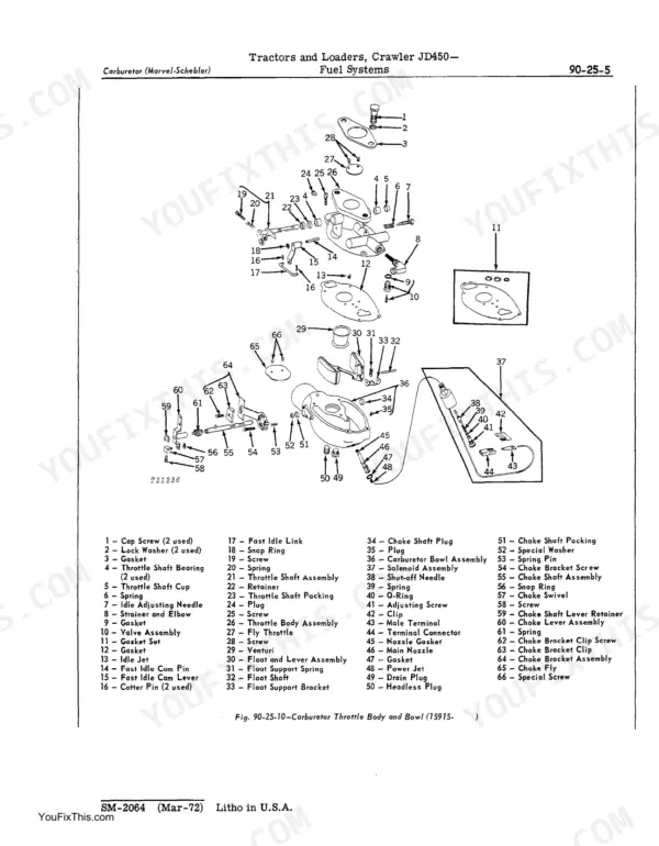
| Fuel Systems | 145-186 | Descirption and Fuel Specifications, Fuel Tank, Fuel Transfer Pump and Fuel Filters, Air Intake System, Carburetor (Marvel-Schebler), Fuel Injection Pumps |
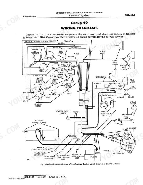
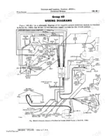
| Electrical System | 187-240 | Fundamentals of Alternator Charging Circuits, Electrical Tests on the Tractor, Ignition System (Gasoline Tractors), Starters, Battery, Wiring Diagrams, Specifications |
| Engine Clutch | 241-248 | Clutch Assembly, Clutch Controls and Clutch Housing |
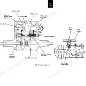
| Constant Mesh Transmission | 249-302 | Description and Operation, Shifter Mechanism, Range Change Unit, Speed Change Unit and Ring Gear and Hub Assembly, Constant Mesh Transmission Specifications |
| H-L-R Transmission | 303-358 | Description and Operation, Shifter Mechanism, Range Change Unit, Speed Change Unit and Ring Gear and Hub Assembly, H-L-R Transmission Specifications |
| Final Drives, Steering Clutches, and Brakes | 359-372 | Description and Adjustment, Final Drives, Steering Clutches and Brakes, Steering Clutch Pressure Plate, Specifications |
| Power Steering System | 373-386 | Description and Operation, Power Steering Pump, Power Steering Cylinders, Power Steering Reservoir |
| Track System | 387-408 | Description and Adjustment, Tracks, Track Carrier Assembly, Specifcations |
| Power Take-Off and Winch Drive | 409-412 | PTO Drive Assembly, Winch Drive Components, Drive Shaft, Sprocket, Belt Tension Adjustment |
| No. 3325 Power Winch | 413-442 | Description and Operation, Winch Hydraulic Pump, Control Valve, And Filter, Winch Housing and Component Parts, Winch Fairlead Assembly, Winch Specifications |
| No. 3320 Manual Winch | 443-472 | Description and Operation, Winch Control Valve and Accumulator, Winch Housing and Component Parts, Winch Fairlead Assembly, Specifications |
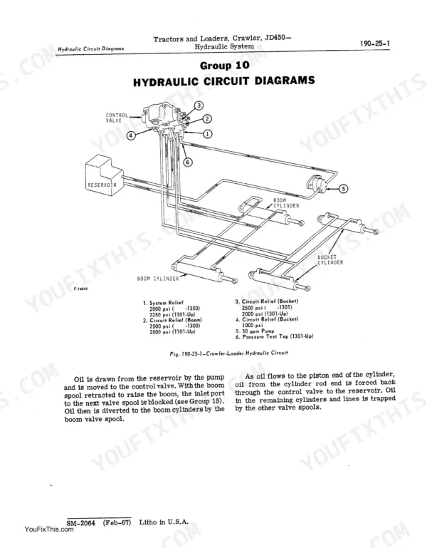
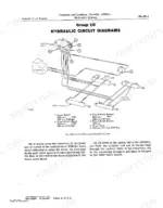
| Hydraulic System | 473-520 | Hydraulic Pump (15 GPM), Hydraulic Pump (30 GPM), Loader Control Valve, Hydraulic Cylinders, Hydraulic Circuit Diagrams, Testing the Loader Hydraulic System, Hydraulic Components |
| Loader Main Frame, Boom, and Buckets | 521-534 | Loader Main Frame and Boom, Digging Bucket, Drott 4-In-1 Bucket |
| Special Service Tools | 561-566 | Special Tool List, Part Numbers, Tool Applications, Service Tool Procedures |
Quick Reference Specifications
| Specification | Value | Page |
|---|---|---|
| All Models | ||
| Cylinder head bolts torque | 110 ft-lbs | p. 49 |
| Track adjusting cylinder quad ring seal and back-up washer replacement | Replace if necessary | p. 400 |
| Alternator Voltage Output at 75°F. | 14.4 volts | p. 239 |
| Alternator Field Current | 2-2.5 amps | p. 239 |
| Wiring harness replacement | Replace if excessively frayed or worn insulation | p. 194 |
| Wiring replacement | Install new wiring | p. 552 |
| Clutch housing to transmission case cap screws torque | 300 ft-lbs | p. 245 |
| Right and left side frames to clutch housing cap screws torque | 300 ft-lbs | p. 21 |
| Coolant bubbles indication | Leakage of cylinder pressure past cylinder head gasket into coolant | p. 49 |
| tractors 46158-Up | ||
| Boom cylinder wear ring replacement (tractors 46158-Up) | Replace if necessary | p. 503 |
| engine serial no. -22564 | ||
| Oil pressure normal range (engine serial no. -22564) | 30 to 40 psi | p. 125 |
| engine serial no. 22565-up | ||
| Oil pressure normal range (engine serial no. 22565-up) | 45 to 65 psi | p. 125 |
John Deere JD450 Common Problems This Manual Covers
JD450 crawler oil pressure gauge reading zero or below normal range at operating speed
Check oil level first, then run the engine to full operating temperature. Normal gauge range per page 125 is 30 to 40 psi for serial no. -22564 engines, or 45 to 65 psi for serial no. 22565-up. If pressure stays low, remove and inspect the oil pump and pickup screen for blockage before condemning internal bearings.
Manual Section: Engine Lubrication System p. 125Coolant bubbles visible in radiator or overflow with engine running at idle
Check the pressure cap and confirm coolant isn't dropping externally. Persistent bubbling with no visible leak points to combustion gas entering the coolant past the head gasket. Remove the cylinder head, inspect the gasket and fire deck for warping, and retorque head bolts to 110 ft-lbs in the sequence on page 49.
Manual Section: Basic Engine p. 49Clutch slips or chatters under load after clutch housing or transmission service
Check clutch adjustment per the Engine Tune-Up section starting on page 43. If the clutch housing was recently reinstalled, verify housing-to-transmission case cap screws are torqued to 300 ft-lbs per page 245, and side frame-to-housing screws to 300 ft-lbs per page 21. A chatter that persists after correct torque usually indicates oil-contaminated friction surfaces.
Manual Section: Engine Clutch p. 245Dash ammeter shows discharge or battery draining with engine running above idle
Inspect the alternator belt deflection; it should measure 3/4 inch under 20 lbs. of force per page 206. Check alternator brush length and replace the brush assembly if brushes extend less than 1/4-inch beyond the holder per page 207. Test field current at the alternator: it should read 2 to 2.5 amps per page 239.
Manual Section: Electrical System p. 206Hydraulic loader won't raise to full height or cylinder loses pressure under load
Allow hydraulic oil to reach operating temperature of 150 to 180°F before testing per page 516. On loaders serial 1301-up, verify system pressure at 2,250 psi at 2,500 engine rpm per page 13. If pressure falls short, inspect the loader control valve for worn seals and test the hydraulic pump for internal bypass before disassembly.
Manual Section: Hydraulic System p. 13Frequently Asked Questions
How to reset steering clutches on John Deere JD450?
To reset steering clutches, pull back hard on both steering levers, then release them to take up any slack in linkage. Then, loosen the jam nut and adjust the large nut on each steering clutch operating rod to obtain 1-1/4 to 1-1/2 inches of free travel for manual steering or 1-1/2 to 2 inches for power steering. Block up the levers to eliminate free travel, insert pins or bolts between steering levers and stops on the platform to hold them in the correct position, and then tighten the brake band adjusting screw until tight when not in detent (1/4 turn past detent). p. 62
What are the torque specs for lower cap screws on John Deere JD450?
For engine installation, tighten the lower cap screws attaching the clutch housing to the engine to 170 ft-lbs torque. When installing the clutch housing, tighten four cap screws from the bottom of the right and left side frames to spacers to 170 ft-lbs. p. 17
Why does my John Deere JD450 stop after 5-10 minutes?
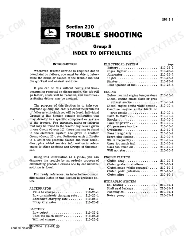
If the engine runs irregularly or stalls frequently, possible causes include low coolant temperature, clogged fuel filters (diesel or gasoline), water, dirt, or air in the fuel system, dirty or faulty injectors (diesel), improper carburetor setting, or defective thermostat. Remedies involve checking and adjusting these components, such as replacing the first-stage filter element and bleeding the fuel system, or replacing the thermostat. p. 538
How to reset neutral safety latch on JD450?
To reset the neutral safety latch, adjust the starter safety switch by installing the maximum number of washers under it that still allow starting the engine with the reverser lever locked in neutral. The cam arm in the transmission housing must press against the safety switch to close the circuit. The maximum torque for the starter safety switch is 35 ft-lbs. p. 196
Is this John Deere JD450 Service Manual a digital download?
This is a 572-page searchable PDF ready for immediate download. Works on any device, so pull it up on your phone while you're under the hood. No shipping, no waiting.
Can I print pages of this manual for my own shop?
Yes. Print the pages you need for the job in your own shop, and bin them when they get greasy.








Reviews
There are no reviews yet.