
This 953-page Claas repair manual covers the Lexion 405 to 460 combine harvesters section by section, and it is a workshop book rather than an operator's guide: every chapter is a removal, installation or adjustment procedure. You get the threshing mechanism (drum, concave, preconcave, stone trap, reduction gearbox), the separation side (impeller, intensive separation, straw walkers, sieve pan and its 3-D control), the grain path (feed rake conveyor, elevators, grain tank unloading), the drives (cutterbar, chopper, fan, left and right belt banks, hydrostatic motors, manual gearbox), the hydraulics down to the individual cylinders and valve combinations, plus steering, axles, brakes, air conditioning and the full tightening-torque tables.
What's Inside This Claas Lexion 405 to 460 Repair Manual
| System | Pages | Key Topics |
|---|---|---|
| General | 1-4 | Introduction, Introduction to the Claas Repair Manual, Key to Symbols |
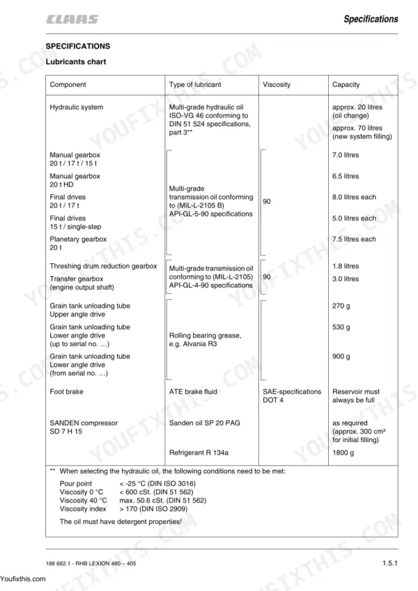
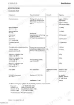
| Specifications | 5-6 | Lubricants Chart, Hydraulic System Oil Type and Capacity, Engine Oil, Gearbox Capacities, Grease Points, Viscosity Grades |
| General Repair Information | 7-10 | Reason of Damage, Spare Parts, Engine, Gearboxes, Alternator, Tensioning the Steel Roller Chains, Taper Ring Fasteners, Self-Locking Bolts |
| D Sieve Pan Control System | 11-12 | Adjusting the 3-D Sieve Pan Control System, Adjusting Pivot Arm |
| Sectional View of Machine | 13-16 | Sectional View of the Machine, Crop Flow Path, Component Layout, Lexion 460 to 405 |
| Drive Diagram | 17-18 | Drive Diagram Left-Hand and Right-Hand, Threshing Drum Drive, Impeller Drive, Main Intermediate Drive, Straw Walker Drive Shaft, V-Belt Routing |
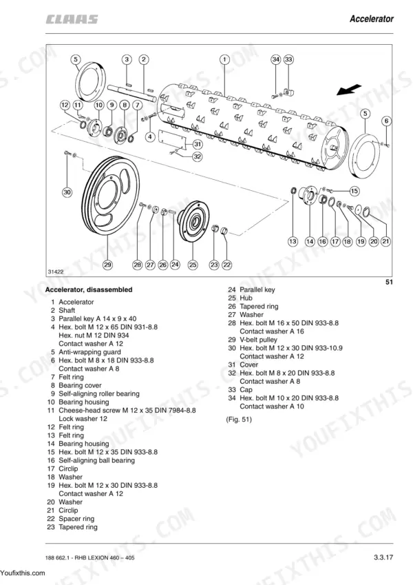
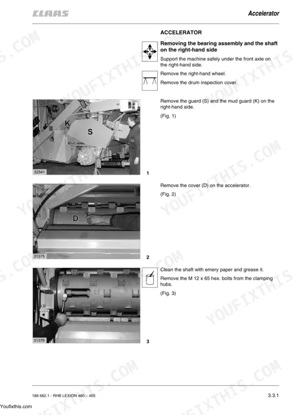
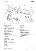
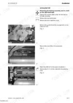
| Accelerator | 19-40 | Removing the Bearing Assembly and the Shaft on the Right-Hand Side, Disassembling the Right-Hand Bearing Assembly, Assembling the Right-Hand Bearing |
| Air Conditioner | 41-72 | Important Instructions Regarding the Compressor-Type Air Conditioning System, Important Instructions Regarding the Installation of Parts in the Compressor-Type Air Conditioner |
| Parking Brake and Brake Lining | 73-76 | Parking Brake – Replacing the Brake Linings, Bleeding the Brake System, Disc Brake – Changing the Brake Pads, Removing a Brake Calliper, Installing a Brake Calliper |
| Chaff Spreader | 77-80 | Assembling the Chaff Spreader |
| Chopper Drive | 81-98 | Removing the Stage 1 Chopper Drive V-Belt Pulley, Stage 1 Chopper Drive V-Belt Pulley |
| Cleaning Fan | 99-112 | Removing the Bearings of the Cleaning Fan, Cleaning Fan Bearing |
| Cooling System | 113-118 | Removing the Intercooler, Installing the Intercooler, Removing the Radiator, Installing the Radiator |
| Cutterbar Drive | 119-182 | Removing the Front Pulley of Cutterbar Drive, Installing the Front Pulley of Cutterbar Drive, Removing the Deflection Pulley of Cutterbar Drive |
| Drive Axle | 183-188 | Removing the Drive Axle, Installing the Drive Axle, Bleeding the Shifter Piston |
| Drive Belts | 189-192 | Drive System Diagram |
| Engine | 193-202 | Removing the Engine, Installing the Engine, Tightening Torque M 16, Tightening Torque M 10 |
| Engine Electric System | 203-204 | Alternator, Starter Motor, Engine Wiring Precautions, Battery Connections |
| Engine Output | 205-226 | Removing the Engine Output Pulley, Installing the Engine Output Pulley, Removing the Transfer Gearbox, Disassembling the Transfer Gearbox, Removing the Drive Shaft |
| Fan Drive | 227-268 | Removing the Stage 1 Fan Drive V-Belt Pulley, Stage 1 Fan Drive V-Belt Pulley, Disassembled (Tapered Ring, Parallel Key), Installing the Stage 1 Fan Drive V-Belt Pulley |
| Feed Rake Conveyor | 269-310 | Removing the Feed Rake Conveyor, Installing the Feed Rake Conveyor, Removing the Intercepting Piece, Installing the Intercepting Piece |
| Final Drives | 311-340 | Removing the Final Drive Gearbox, Disassembling the Final Drive Gearbox, Remove Cap and the O-Ring, Drive Out the Double Expansion Pin and Unscrew the Castellated Nut |
| Foot Brake | 341-342 | Foot Brake Pedal, Brake Master Cylinder, Bleeding the Brake Circuit, Brake Line Replacement, Pedal Free Play |
| Fuel System | 343-344 | Removing the Fuel Tank, Installing the Fuel Tank, Bleed the Fuel System |
| Grain Elevator | 345-370 | Removing the Clean Grain Elevator Chain, Remove the Two Cover Plates at the Elevator Head, Pull the Elevator Chain Out From the Top, Installing the Clean Grain Elevator Chain |
| Grain Tank Unloading | 371-412 | Removing the Grain Tank Cross Auger, Remove the Sprocket Using a Suitable Puller, Remove the Circlip From the Sprocket, Unscrew the Hex Bolts From the Bearing Plate |
| Grain Tank Unloading Drive | 413-416 | Grain Tank Unloading Drive Belt, Drive Pulley, Tensioner, Unloading Auger Gearbox Drive, Tightening Torque |
| Hydraulic Cylinder – Steering Hydraulics | 417-428 | Removing the Steering Cylinder, Disassembling the Steering Cylinder, With the Cylinder Barrel Chucked, Turn the Cylinder Head |
| Hydraulic Cylinders – High-Pressure Hydraulic Circuit | 429-464 | Removing the Cutterbar Cross Levelling Hydraulic Cylinders, Disassembling the Cutterbar Cross Levelling Hydraulic Cylinders |
| Hydraulic Cylinders for Low-Pressure Hydraulics | 465-510 | Removing the Threshing Mechanism Engagement Hydraulic Cylinder, Disassembling the Threshing Mechanism Engagement Hydraulic Cylinder |
| Hydraulic Pumps | 511-518 | Removing the Chaff Spreader Hydraulic Pump, Remove the Hex Nut From the V-Belt Pulley, Using a Suitable Three-Legged Puller, Remove the V-Belt Pulley |
| Hydrostatic Fixed Displacement Motors | 519-534 | Removing the Ground Drive Hydrostatic Fixed Displacement Motor, Drain the Hydraulic Oil From the Motor Into a Sufficiently Large Container |
| Impeller | 535-546 | Removing the Right-Hand Impeller Bearing, Unbolt the Jockey Pulley, Remove the Grease Pipe From the Bearing Assembly, Remove the Four M 12 X 35 Hex Bolts From Bearing Assembly |
| Intensive Separation System | 547-552 | Replacing the Agitator Tines, Removing the Control Shaft for the Intensive Separation System, Unbolt Brace, Unbolt the Control Shaft on Both Sides of the Combine and Remove It |
| Left-Hand Drive Belts | 553-590 | Removing the Cutterbar Drive Belt, Relieving the Tension of Cutterbar Drive, Installing and Adjusting the Cutterbar Drive Belt, Removing the Cutterbar Variable-Speed Drive Belt |
| Left-Hand Threshing Mechanism Drive | 591-604 | Removing the Threshing Mechanism Drive Pulley Assembly, Remove the Two Slotted Nuts with the Socket Wrench, Remove the Cylinder and the Six Belleville Springs |
| Maintenance | 605-608 | Hydraulic System, Checking the Oil Level, Changing the Hydraulic Oil, Filling Instructions When Changing the Hydraulic Oil |
| Manual Gearbox | 609-636 | Removing the Manual Gearbox, Unlock the Pin at the Gearshift Linkage and Pull It Out, Unscrew Clamps for Attaching the Hydraulic Hoses, For Servo Gearshift |
| Oil Cooler | 637-640 | Removing the Oil Cooler, Fold Up the Rotary Screen, Remove the Cover From the Air Intake Box, Remove the Stop, Loosen the Catches and Remove the Bearing Plate |
| Parking Brake | 641-642 | Parking Brake Cable, Brake Disc and Caliper, Adjusting the Parking Brake, Removing and Installing the Parking Brake Unit |
| Preparation Floor | 643-646 | Removing the Preparation Floor, Unscrew Cover Completely with the Hinges, Unscrew the Front Rocker Arms From the Preparation Floor and the Machine Frame |
| Returns Elevator | 647-660 | Removing the Returns Elevator Chain, Turn the Elevator Chain Until the Chain Connector Is at the Bottom, Separate the Chain at the Chain Connector |
| Right-Hand Drive Belts | 661-692 | Removing the Intensive Separator System Drive Belts, Installing and Adjusting the Intensive Separator System Drive Belts, Removing the Fan Intermediate Drive Belt |
| Right-Hand Threshing Mechanism Drive | 693-716 | Removing the Threshing Drum Variable-Speed Pulley Assembly, Unscrew the M 16 X 60 Hex Bolt and Remove Together with Thrust Washer |
| Rocker Arm Drive | 717-720 | Removing the Intermediate Drive Shaft for the, Installing the Intermediate Drive Shaft for the, Tightening Torque, Checking and Adjusting the Alignment of Prepara- |
| Rotary Screen | 721-732 | Removing the Rotary Screen, Assembling and Installing the Rotary Screen, Installing and Adjusting the Rotary Chaff Screen, Adjusting the Trough and the Lateral Panel, Removing the Fan Drive, Removing the Fan Drive Belt, Installing the Fan Drive |
| Rotary Screen Drive | 733-738 | Removing the Rotary Screen Drive, Removing the Fan Drive Belt, Removing the Radiator Chaff Screen Intermediate Drive, Assembling and Installing the Rotary Screen, Installing and Adjusting the Rotary Chaff Screen, Installing and Adjusting the Fan Drive Belt, Removing the Fan Drive |
| Safety Rules | 739-742 | Fitting and Retrofitting of Ancillary Equipment Which |
| Sieve Pan | 743-766 | Removing and Installing the Sieves, Removing the Upper Sieves, Removing the Lower Sieves, Installing the Sieves, Tightening Torques of Axial Mountings for the, Checking the Identical Positions of Frogmouth, Removing the 3-D Upper Sieve Frame |
| Sieve Pan Drive | 767-772 | Removing the Sieve Pan / Straw Walker Drive, Removing the Sieve Pan / Straw Walker Intermediate, Removing the Sieve Pan Drive Belt, Removing the Straw Walker Drive Belt, Installing the Sieve Pan / Straw Walker Drive, Installing and Adjusting the Straw Walker Drive Belt, Installing and Adjusting the Sieve Pan Drive Belt |
| Steering | 773-790 | Removing the Steering Column, Removing the Gas Strut, Removing the Steering Tube with the Shaft, Assembling the Steering Tube, Assembling the Steering Column, Tightening Torque, Installing the Steering Column |
| Steering Axle | 791-808 | Removing the Wheel Bearing, Installing the Wheel Bearing, Adjusting Both Taper Roller Bearings, Tightening Torque, Installing the Wheel Bearings for Machines, Setting Up the Taper Roller Bearings, Removing the Stub Axle |
| Steering Axle 2 | 809-823 | Removing the Wheel Bearing, Assembling the Wheel Bearings, Removing the Stub Axle, Assembling the Stub Axle, Setting the Tracking, Setting the Steering Axle Stroke, Removing the Stub |
| Straw Chopper | 824-837 | Removing the Right-Hand Straw Chopper, Installing the Right-Hand Straw Chopper, Tightening Torque, Removing the Left-Hand Straw Chopper Bearing, Removing the Straw Chopper Drive Belt, Installing the Straw Chopper Drive V-Belt Pulley, Installing the Left-Hand Straw Chopper Bearing |
| Straw Spreader Drive | 838-849 | Removing the Straw Spreader Bearing Housing, Removing the Straw Spreader Drive Belt, Assembling the Straw Spreader Bearing Housing, Installing the Straw Spreader Bearing Housing, Tightening Torque, Installing and Adjusting the Straw Spreader Drive |
| Straw Walker | 850-861 | Removing the Straw Walker Racks, Removing the Under-Walker Return Floor, Installing the Straw Walker Racks, Installing the Under-Walker Return Floor, Removing the Front Straw Walker Crankshaft, Installing the Front Straw Walker Crankshaft, Removing the Rear Straw Walker Crankshaft |
| Threshing Concave | 862-883 | Removing the Stone Trap, Installing the Stone Trap, Removing the Preconcave, Removing the Feed Rake Conveyor, Installing the Preconcave, Tightening Torque, Setting the Basic Concave Adjustments |
| Threshing Drum | 884-901 | Removing the Right-Hand Drum Bearing, Removing the Accelerator Drive, Removing the Threshing Drum Reduction, Installing the Right-Hand Drum Bearing, Installing the Threshing Drum, Installing and Adjusting the Accelera-, Removing the Left-Hand Drum Bearing |
| Threshing Drum Reduction Gearbox | 902-915 | Removing the Threshing Drum Reduction, Removing the Threshing Drum Drive Belt, Removing the Accelerator Drive Belt, Assembling the Threshing Drum Reduction Gearbox, Tightening Torque, Installing the Threshing Drum Reduction, Installing and Adjusting the Accelerator Drive Belt |
| Threshing Mechanism Intermediate Drive | 916-919 | Removing the Right-Hand Intermediate Drive, Removing the Threshing Drum Variable-Speed Pulley, Removing the Stage 1 Fan Drive V-Belt Pulley, Installing the Right-Hand Intermediate Drive, Installing the Stage 1 Fan Drive V-Belt Pulley, Installing the Threshing Drum Variable-Speed, Removing the Left-Hand Intermediate Drive |
| Under-Walker Return Floor | 920-921 | Removing the Under-Walker Return Floor, Installing the Under-Walker Return Floor |
| Valve Combinations | 922-949 | Removing the Feeder Reversing 3/2-way Valve, Removing the Cutterbar Cross Levelling, Removing the Concave Adjustment Pressure, Assembling the Concave Adjustment Pressure, Removing the Cutterbar and Threshing Drum, Installing the Cutterbar and Threshing Drum, Removing the Threshing Drum Variable-Speed |
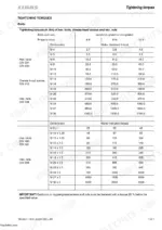
| Tightening Torques | 950-953 | Tightening Torques for Unions with and Without Copper Sea, Tightening Torques Ma in Nm for Unions, Tightening Torques for Drive Axle and Steering Axle / Rea |
Quick Reference Specifications
| Specification | Value | Page |
|---|---|---|
| All Models | ||
| Feed rake chain bolt tightening torque | 195 Nm | p. 290 |
| Chaff spreader hydraulic pump assembly cheese-head screws tightening torque | 35 Nm | p. 513 |
| Chaff spreader hydraulic pump V-belt pulley hex. nut tightening torque | 50+10 Nm | p. 513 |
| Steering system circulation pressure limit (to prevent overheating) | approx. 20 bar | p. 782 |
| Hydraulic system oil capacity (new system filling) | 70 litres | p. 5 |
| Refrigerant R 134a filling quantity | 1800 g | p. 43 |
| LEXION 460 / 450 / 440, LEXION 430 / 420 / 415, LEXION 410 / 405 | ||
| Working hydraulics - Lifting hydraulics set pressure | 175+15 bar | p. 6 |
| Working hydraulics - Steering set pressure | 150+15 bar | p. 6 |
| Manual gearbox 20 t / 17 t / 15 t | ||
| Manual gearbox (20 t / 17 t / 15 t) capacity | 7.0 litres | p. 5 |
| all LEXION models | ||
| Working hydraulics Lifting hydraulics pressure | 175+15 bar | p. 6 |
| Working hydraulics Steering pressure | 150+15 bar | p. 6 |
Claas Lexion 405 to 460 Common Problems This Manual Covers
Claas Lexion feed rake conveyor stops or jerks under heavy crop loads, chain skips
Pull the feed rake conveyor cover on page 269 and check the chain for stretched links or a cracked drive sprocket. Inspect the upper feed rake shaft slip clutch, torqued to 840 ± 40 Nm at the factory per page 953, for slippage under load. Tighten chain retaining bolts to 195 Nm and swap any bent tines before returning to the field.
Manual Section: Feed Rake conveyor p. 269Engine overheating under load with radiator running hot despite coolant reservoir showing full
Pull the rotary screen and check the radiator core on page 113 for chaff packing before you condemn the water pump. Verify the thermostat opens fully and confirm coolant level in the header tank. On PERKINS 1306-9T engines the coolant filter must be an original cartridge, per page 118; a non-OEM filter restricts flow and drives temperature up fast.
Manual Section: Cooling system p. 113Hydraulic system loses pressure or cylinders move slowly during heavy field operation
Hook a gauge to the low-pressure solenoid valve block and confirm the PRV holds at 21+1 bar at 4.0 l/min flow, per page 944. If lifting hydraulics fall below the 175+15 bar working pressure spec, pull the double pump assembly on page 511 and verify the cheese-head mounting screws are torqued to 35 Nm; a loose housing bleeds pressure fast.
Manual Section: Valve combinations p. 944CEBIS display shows communication error or goes completely blank mid-season during operation
Trace the harness back through the Engine Electric system starting on page 203 and check every connector for corrosion or a backed-out pin before you condemn the CEBIS module itself. Confirm alternator output stays steady under load; a fluctuating supply voltage will drop CEBIS communication and blank the display even with the module itself working fine.
Manual Section: Engine Electric system p. 203Hydraulic cylinders leak fluid externally after two to three seasons of field use
Pull the cylinder from the High-Pressure Hydraulic circuit section starting page 429 and inspect the rod seal and wiper ring for scoring. Torque the M12 x 1.5 O-ring fittings to 16+5 Nm per page 951; an under-torqued fitting is the most common source of a slow weep that turns into a steady drip after a couple seasons.
Manual Section: Hydraulic Cylinders – High-Pressure Hydraulic circuit p. 429Frequently Asked Questions
What are the torque specs for CLAAS Lexion 450 engine bolts?
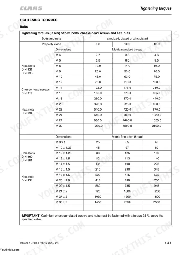
The manual provides general tightening torques for hex. bolts, cheese-head screws, and hex. nuts based on their size and property class. For example, an M16 bolt with property class 8.8 should be tightened to 195.0 Nm. Specific torque values for 'engine bolts' for a Lexion 450 are not listed as a single item, but general bolt torques are available. p. 950
Torque specification for CLAAS Lexion 420 hydraulic pump mounting bolts
For Lexion 430 – 405 models, the tightening torque for the ground drive hydraulic pump mounting bolts is 78 Nm. For Lexion 460 – 440 models, the torque is 370 Nm. This torque applies when introducing the hydraulic pump into the transfer gearbox and bolting it into position. p. 517
What are the replacement specifications for Conveyor chain and sprockets?
When installing the bottom feed rake roller, chain connectors should be secured with new split pins. The chains must be tensioned evenly on both sides so that the feed rake slats just touch the runners. Stops can be relocated by engaging the dowel pin in hole (1) for small grains and hole (2) for maize. p. 293
What are the replacement specifications for Hydraulic pump and seals?
For the chaff spreader hydraulic pump, during assembly, it is necessary to check the seal (2), back-up ring (3), and slide plate (4) and replace them if necessary. After checking, the gears (5 and 6) are inserted into the housing parts (1, 7 and 8) and the pump is assembled with cheese-head screws (Z). p. 513
What is the hydraulic oil capacity for the CLAAS Lexion hydraulic system?
The hydraulic system has an approximate capacity of 20 litres for an oil change. For a new system filling, the capacity is approximately 70 litres. This ensures proper operation and maintenance of the hydraulic components. p. 5
How will I receive this Claas Lexion 460 & variants Repair Manual?
You get a 953-page searchable PDF that downloads instantly after checkout. Open it on your laptop, tablet, or phone, and bring it right to the shop floor.
Can I print specific sections of this Claas Lexion 460 & variants Repair Manual?
Yes. Print the pages or sections you need for your own shop use. Any standard printer works.
![International 444 Tractor, International 444 Tractor... [list], gearshift pattern diagram, driving and starting procedures.](https://youfixthis.com/wp-content/uploads/2026/06/international-444-tractor-tractor-operator-manual-1082661r2-operations-11-64x83.webp)


Reviews
There are no reviews yet.