

Part of the John Deere Repair Manuals.
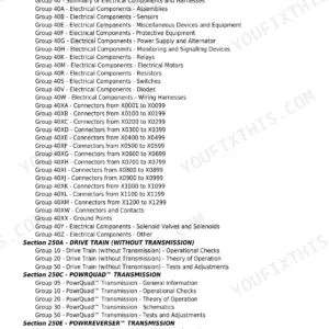
This is the complete John Deere factory Diagnosis and Tests Service Manual (TM400719) for the 6230, 6330, 6430, 7130 and 7230 tractors sold in North America, covering machines built from the 2009 serial number break onward. All 3,315 pages are organized around what a shop technician actually needs: how to read and clear BCU, ECU, EPC and PRC control unit fault codes, how to trace observable symptoms through the transmission and hydraulic system, how to run the engine operational checks and fuel/cooling tests, and how to use the full wiring diagrams in Section 240 to chase an intermittent electrical fault to its source. This is the same document a John Deere dealer technician opens at the workstation when a machine comes in with a code on the CommandCenter display.
What's Inside This John Deere 6230, 6330, 6430, 7130, 7230 Manual
| System | Pages | Key Topics |
|---|---|---|
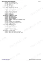
| General Information | Safety Measures, General References, Circuit/Harness Test Worksheet, Tabular Diagnostic Procedures, Troubleshooting Unsolved Problems | |
| Diagnostic Trouble Codes | Bcu Control Unit Codes, ECU Control Unit Codes, Epc Control Unit Codes, Prc Control Unit Codes | |
| Observable Symptoms | - | |
| System Diagnostics | Electronics Diagnostics, PowrQuad Transmission Diagnostics, Hydraulic System Diagnostics | |
| Engine | General Information, Operational Checks, Tests and Adjustments | |
| Fuel, Air Intake, and Cooling Systems | Fuel System Tests, Air Intake System, Cooling System, Cold-Weather Starting Aids, Tests and Adjustments | |
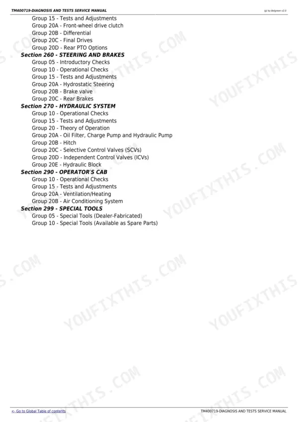
| Electrical System | Starting Motor and Charging, Instrument Unit, Lights and Worklights, Air Conditioning, BCU/EPC/PRC Circuit Groups, Wiring Harnesses, Component Locations | |
| Electronic Control Units | Bcu Operational Checks, ECU Operational Checks, Epc Operational Checks, Prc Operational Checks, Address Readouts | |
| SyncroPlus Transmission | Operational Checks, Tests and Adjustments, Shift Quality Diagnostics | |
| PowrReverser Transmission | Operational Checks, Tests and Adjustments, Electronic Reverser Control | |
| PowrQuad Transmission | Operational Checks, Tests and Adjustments, Clutch Pack Diagnostics | |
| Drive Train | Front Axle, Differential, Final Drives, Four-Wheel Drive | |
| Steering and Brakes | Power Steering System, Brake System, Tests and Adjustments | |
| Hydraulic System | Hydraulic Pump, Control Valves, 3-Point Hitch, Remote Cylinders, Tests and Adjustments | |
| Operator Cab | Climate Control, Instrument Panel, Operator Station Components | |
| Special Tools | Diagnostic Tools, Test Equipment, Tool Specifications |
Quick Reference Specifications
| Specification | Value | Page |
|---|---|---|
| All models | ||
| Fuel system max pressure (before injection pump) | 0.6 bar (60 kPa; 8.7 psi) | |
| Air filter restriction - warning threshold | 6.9 kPa (69 mbar; 0.86 psi) | |
| Air intake restriction - normal operating range | 5.9 to 6.9 kPa (59 to 69 mbar) | |
| Battery supply voltage (engine running) | 12.5 to 15.4 V | |
| Battery supply voltage (engine off) | 11.2 to 12.7 V | |
| Enable pressure sensor activation threshold | 100 kPa (1 bar; 14.5 psi) | |
| Cooling system normal pressure range | 50 to 60 kPa (0.5 to 0.6 bar; 7 to 8.7 psi) | |
| Coolant thermostat housing torque | 4 to 5 N.m (3 to 3.7 lb-ft) | |
| 6230, 6330, 6430, 7130, 7230 | ||
| OEM Number | TM400719 (November 2013) | |
John Deere 6230, 6330, 6430, 7130, 7230 Common Problems This Manual Covers
BCU hitch control fault code returns after clearing, hitch operates erratically or fails to respond
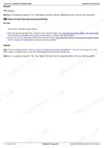
Access address BCU105 to check draft sensor signal voltage - the valid range is 0.50 to 4.50 V. If the voltage is above 4.75 V the draft sensor circuit has a short or open; check leads 531, 873 and 884 between the BCU and sensor B41 for damage or corrosion. Repair the circuit before clearing the code or it will return on the next hitch operation. Full procedure is in Section 211, Group BCU.
Manual Section: Diagnostic Trouble Codes - BCUEngine shuts down or loses power under load, oil pressure warning active
Verify battery voltage is 12.5 V or higher with the engine running and that the enable pressure sensor reads above 100 kPa (1 bar) within two seconds of starting. Check the oil filter and cooler for debris blockage - contaminated oil bypassing a clogged filter base is the most common cause of oil pressure loss on these engines. Section 220, Group 10 covers the operational checks in sequence.
Manual Section: Engine - Tests and AdjustmentsEngine overheats or loses coolant pressure during extended field operation
Test cooling system pressure against the 50 to 60 kPa (0.5 to 0.6 bar) normal range and check the fuel system pressure before the injection pump against the 0.6 bar maximum. Air intake restriction above 6.9 kPa triggers the air filter warning - a clogged primary filter combined with marginal coolant pressure causes thermal runaway under sustained load. Service both the air and coolant systems together per Section 230 before returning the machine to work.
Manual Section: Fuel, Air Intake, and Cooling SystemsIntermittent electrical faults - warning lights flicker, functions drop out, codes appear and disappear
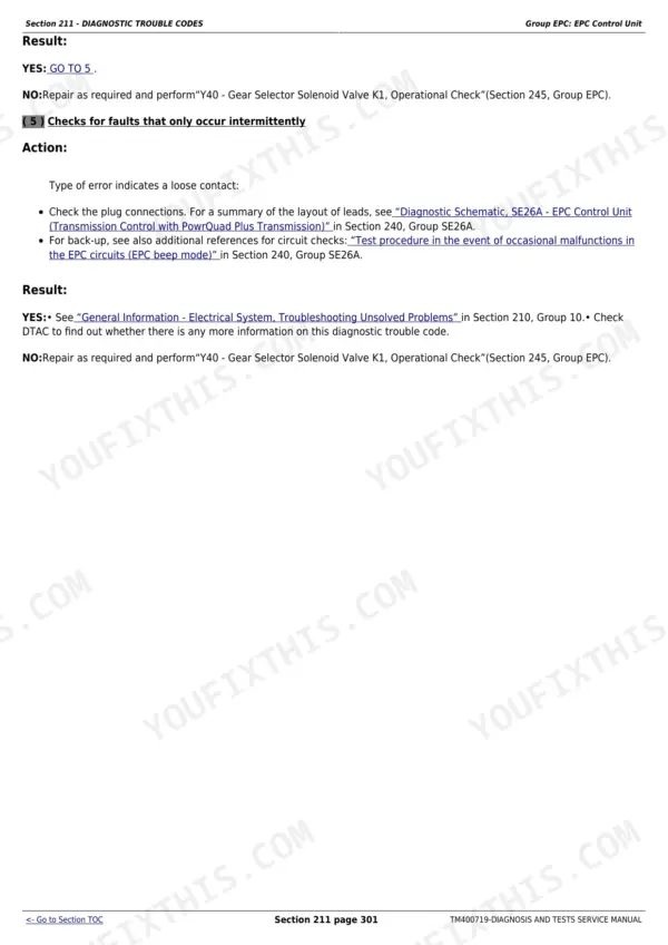
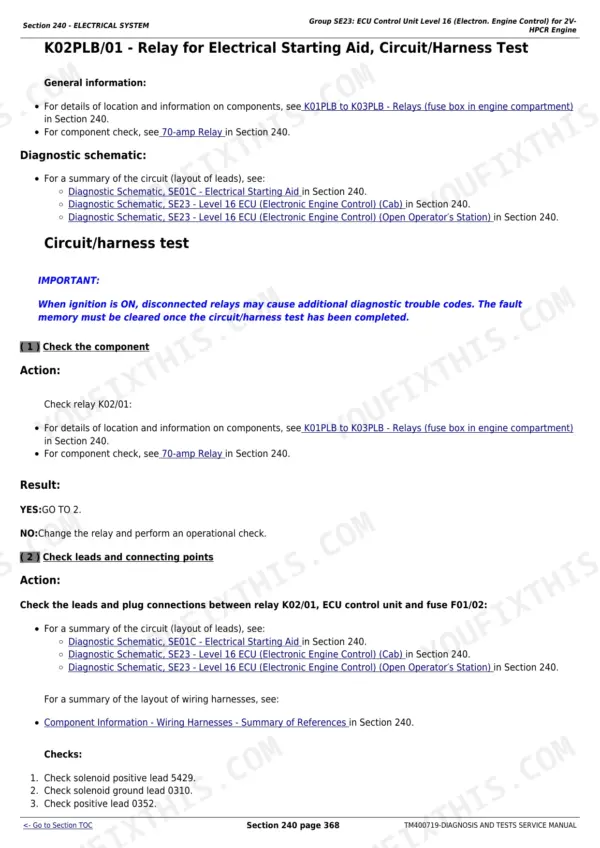
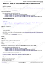
Intermittent faults on these tractors are almost always loose or corroded connector contacts, not failed components. Use the circuit/harness test worksheet in Section 210, Group 10 to document every connector and harness in the affected circuit before testing. Section 240 wiring diagrams (SE01 through SE32 circuit groups) let you trace the exact lead numbers from the control unit pin to the component - verify contact quality at both ends before condemning a sensor or ECU.
Manual Section: Electrical System - Circuit GroupsFrequently Asked Questions
How do I clear diagnostic trouble codes on a John Deere 6230, 6330 or 6430 tractor?
The manual walks through clearing codes via the CommandCenter display using the BCU, ECU, EPC or PRC control unit address menus. The procedure in Section 245, Group 05 covers accessing diagnostic addresses and resetting codes - the key step is confirming the root fault is resolved first, otherwise the code returns immediately on the next operational check cycle.
What does a BCU control unit fault code mean on a John Deere 7130 or 7230?
BCU codes on the 7130/7230 point to faults in the hitch control, 3-point lift, or operator station circuits managed by the Body Control Unit. Section 211, Group BCU lists every BCU code with the exact circuit to test and the specification to measure - supply voltage at 12.5 to 15.4 V running, sensor signal voltage within the 0.50 to 4.50 V valid range. Work through the listed checks in order before replacing the BCU.
How do I test hydraulic lift pressure on John Deere 6330 or 6430?
Section 270 (Hydraulic System) covers the pressure test procedure including valve block, pump output and 3-point circuit pressures. The observable symptom path in Section 212, Group 70 is a good starting point if you have a specific complaint like slow lift or pressure drop after warm-up - it points you directly to the hydraulic test that applies.
Does this manual cover all three transmission options - SyncroPlus, PowrReverser and PowrQuad?
Yes. Sections 250, 251 and 255 each have dedicated operational checks, observable symptom paths and tests for the SyncroPlus, PowrReverser and PowrQuad transmissions respectively. Section 211 DTC codes for EPC and PRC control units cover the electronic side of the PowrQuad and PowrReverser, and Section 245 has the control unit address readouts you need to verify clutch fill times and pressure values during a live test.
What electrical voltage specs does the manual give for diagnosing charging system problems?
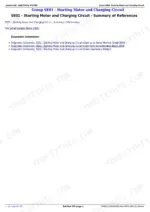
The manual specifies 12.5 to 15.4 V at the control unit supply pins with the engine running, and 11.2 to 12.7 V with the engine off. If the voltage drops below 11.2 V under engine-off conditions, the battery is weak; if it fails to reach 12.5 V within two seconds after start, the charging circuit needs testing per the SE01 Starting Motor and Charging section in Section 240.
Is this John Deere 6230 manual a PDF I download?
This is a 3315-page searchable PDF (94 MB) ready for immediate download. Works on any device, so pull it up on your phone while you're under the hood. No shipping, no waiting.
Does this John Deere 6230 manual allow printing?
Absolutely. No DRM or copy protection. Print the whole manual or just the pages you need. Any home or office printer works.







Reviews
There are no reviews yet.