


All 1,074 pages of this Kioti NX4510–NX6010 Series Shop Manual (OEM #DN60-W00) are factory-written for the 2004–2013 NX4510, NX5010, NX5510, and NX6010H tractors, every variant and cab configuration covered. Inside: complete wiring diagrams with component locations for the HST controller, ECU, and cabin circuits, plus full hydraulic schematics tracing the lift, steering, and remote valve circuits from pump to cylinder. You also get step-by-step disassembly procedures, DTC error codes with action tables, and HST calibration procedures covering pedal adjustment and controller diagnosis. Set your main hydraulic relief to 185 kgf/cm² and steering relief to 145 kgf/cm²: factory numbers, not forum guesses. Every hour your tractor sits costs money. Download now, open on any device, and jump straight to any chapter with built-in bookmarks.
What's Inside This Kioti NX4510–NX6010 Series Manual
| System | Pages | Key Topics |
|---|---|---|
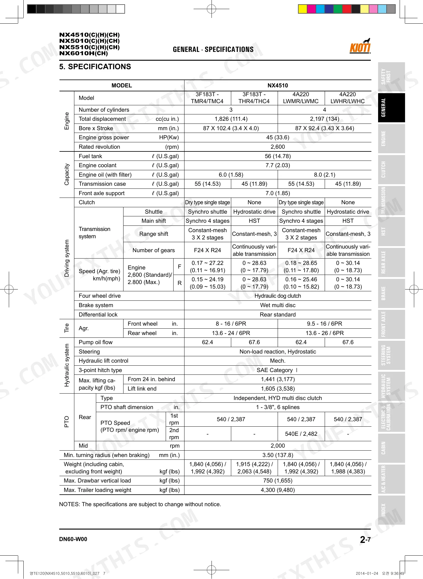
| General | 21-54 | Description for Symbols and Abbreviations, Tractor Exterior View, Identification Number (Tractor Serial Number, Engine Serial Number, Transmission Serial Number), Dimensions |
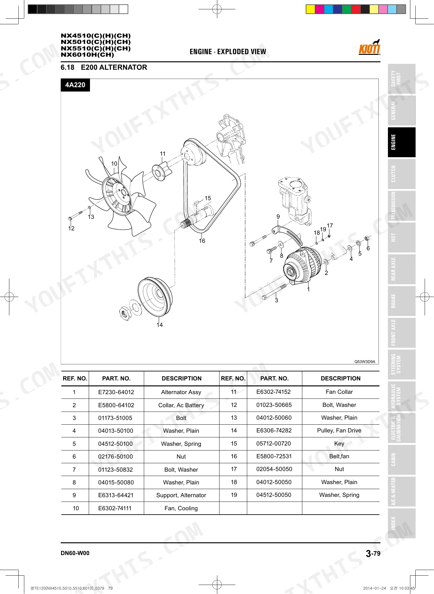
| Engine (1) | 55-164 | Engine Identification (Engine Epa Decal, Engine Number, Assignment Standard for Engine Model Code) |
| Engine (2) | 165-332 | Engine Identification (Engine Epa Decal, Engine Number, Assignment Standard for Engine Model Code) |
| Clutch | 333-348 | Operational Principle |
| Transmission | 349-434 | Structure and Operating Principle (Main Gear Shift & Shuttle System, Operating Principle of Synchronizer, Shuttle, Range Shift Section, Creep Shift Speed Section, Shift Link System, PTO, PTO Clutch Pack, Mid PTO, Calculation for Rear PTO and Mid PTO, Front Wheel Drive) |
| HST | 435-476 | Servicing (Removal and Installation of HST, Removal and Installation of HST Components, Gerneral Information, Components, HST Components & Circuit Diagram, Circuit Diagram, Basic Principle |
| Rear Axle | 477-498 | Servicing and Assembly (Rear Axle Components, Rear Wheel Nut, Rear Differential System, Differential Lock System, Backlash for Differential Pinion and Side Gear, Adjustment, Backlash for Spiral Bevel Pinion and Ring Gear, T227A Spiral Bevel Pinion Shaft |
| Brake | 499-516 | Structure and Operation Principle |
| Front Axle | 517-562 | Structure and Operating Principle (Power Transfer System for Front Axle, Differential System, Load Transfer, Floating Seal) |
| Steering System | 563-588 | Specifications and Tightening Torque (Specifications for Steering System, Tightening Torque for Major Components) |
| Hydraulic System | 589-674 | Structure and Operating Principle (Component Arrangement, Hydraulic Circuit, Components) |
| Electric System | 675-970 | Circuit and Component Location (Overall Circuit Diagram, Location of Electronic Components and Sensors) |
| Cabin | 971-1014 | Components (Interior Devices, External Devices) |
| Air Conditioning | 1015-1062 | Air-Con/Heater Main Spec, Principle of Cooling System, System Flow, Compressor, Receiver-Drier, Condenser, Expansion Valve, Evaporator |
| Index | 1063-1074 | - |
Every system also includes an exploded view.
Quick Reference Specifications
| Specification | Value | Page |
|---|---|---|
| All Models | ||
| Front axle cover (final drive cover) torque | 23.5 ~ 27.5 Nm | p. 519 |
| Differential case cover assembly torque | 39.2 ~ 55.9 Nm | p. 519 |
| Main relief pressure | 185 kgf/cm² (18.13 MPa 2,631 psi) | p. 591 |
| Steering relief pressure | 145 kgf/cm² (14.21 MPa 1,991 psi) | p. 591 |
| HST forward/reverse driving pedal setting condition | Calibration mode is activated when the ignition switch is turned to the ON position for approx. 2 seconds with the brake switch and calibration switch ON | p. 870 |
| HST forward/reverse driving pedal setting illumination order | N → L → N → M → N → H → N → L→ N → M → N → H → N ("N" lamp illuminated lastly) | p. 774 |
| Propeller shaft case, Clutch cover mounting bolt torque | 23.5 ~ 27.4 Nm | p. 351 |
| Spiral bevel gear shaft cocking nut torque | 147.0 ~ 196.1 Nm | p. 351 |
| Charge relief valve opening pressure | 25 kgf/cm² (2.35 MPa) | p. 610 |
| HST relief valve pressure | 380 kgf/cm² (5,404 psi) | p. 611 |
| 3F183T engine models (NX4510, NX5010, NX5510, NX6010) | ||
| Engine Oil Capacity (with filter) | 6.0 L (1.58 U.S.gal) | p. 125 |
| Mechanical models | ||
| Transmission Oil Capacity (Mechanical Model) | 55 L (14.53 U.S.gal) | p. 350 |
Kioti NX4510–NX6010 Series Common Problems This Manual Covers
Kioti NX4510 hydrostatic transmission will not drive correctly and calibration light stays on after warm up.
Activate calibration mode by turning the ignition switch ON for approximately 2 seconds with the brake and calibration switches ON. Review the pedal setting procedures on page 870. If the cruise lamp indicator blinks, the setting is incorrect and requires a full reset.
Manual Section: 영TE120(NX4510,5010,5510,6010)_12장_전기장치 p. 870Weak or unstable hydraulic operation requiring adjustment at the relief valve area under the seat.
Inspect the main relief valve and verify pressure settings. Adjust the main relief pressure to exactly 185 kgf/cm² (18.13 MPa, 2,631 psi) as outlined on page 591. If pressure drops, drain the system and refill with 55 L (14.53 U.S.gal) of approved fluid for mechanical models.
Manual Section: Hydraulic System Troubleshooting p. 591Front wheel drive operation is impossible and abnormal creaking noise comes from the front axle.
Drain the front axle case and inspect for metal shavings. Refill the front axle with exactly 7.0 L (1.85 U.S.gal) of fresh oil as specified on page 518. Torque the front axle cover bolts to 23.5 ~ 27.5 Nm before testing operation under load.
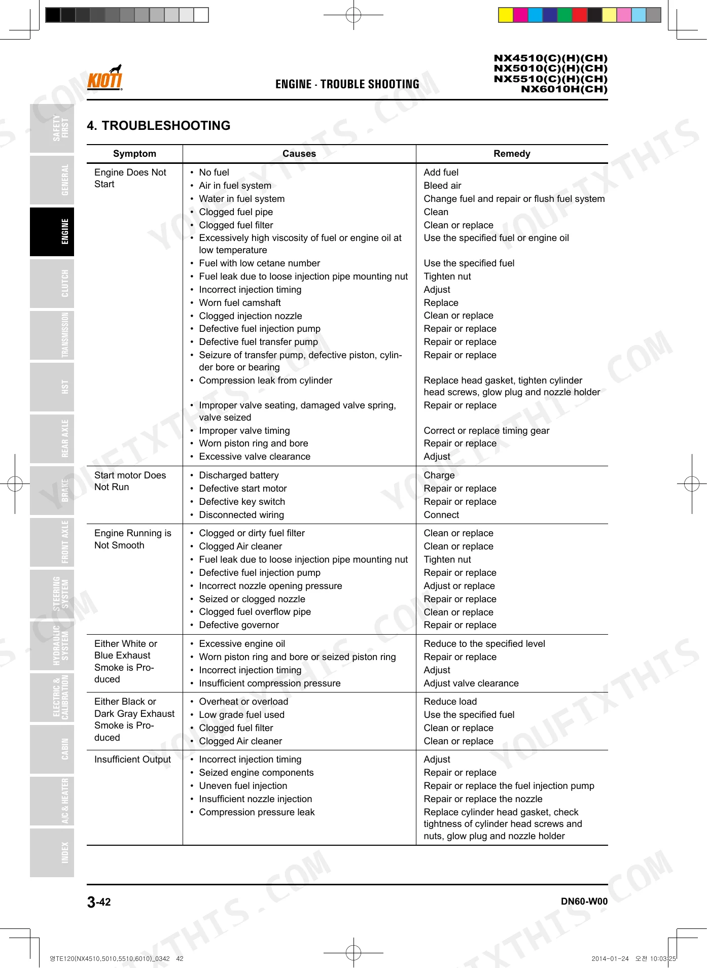
Manual Section: Front Axle Troubleshooting p. 518Engine turns over but will not start or has rough idle in cold weather conditions.
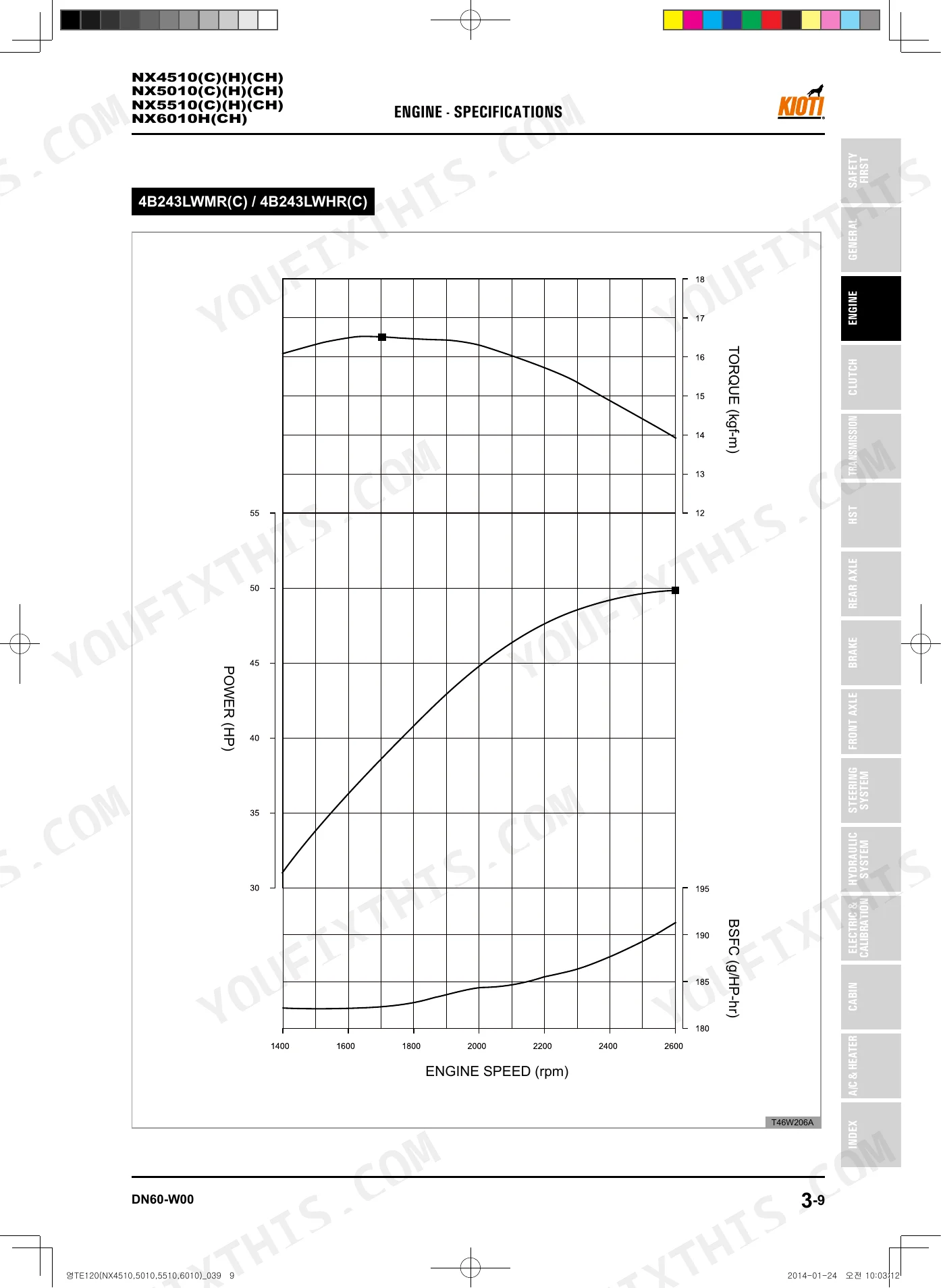
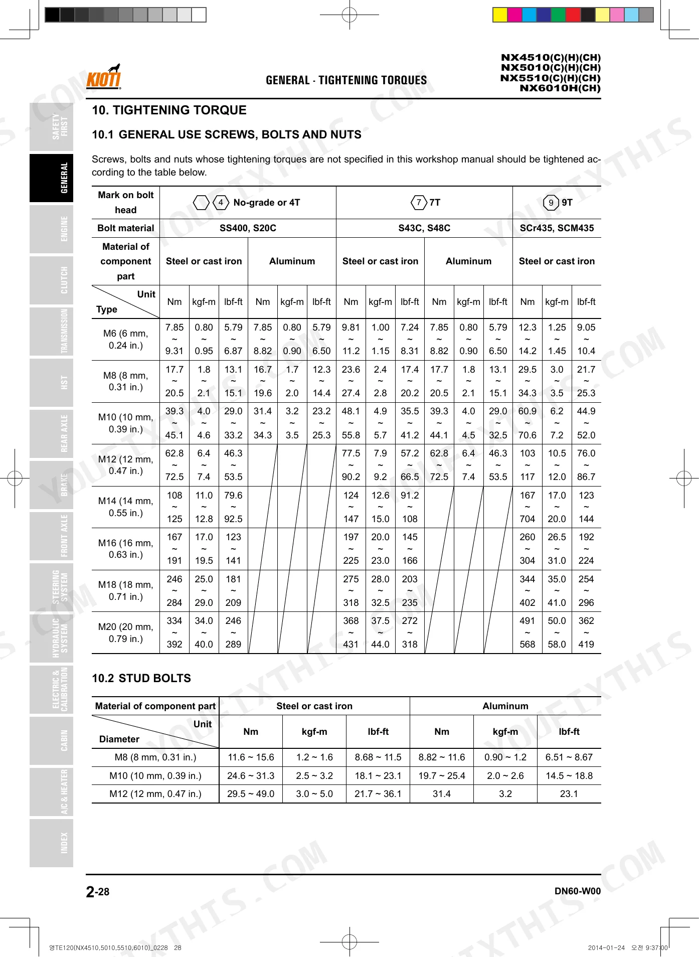
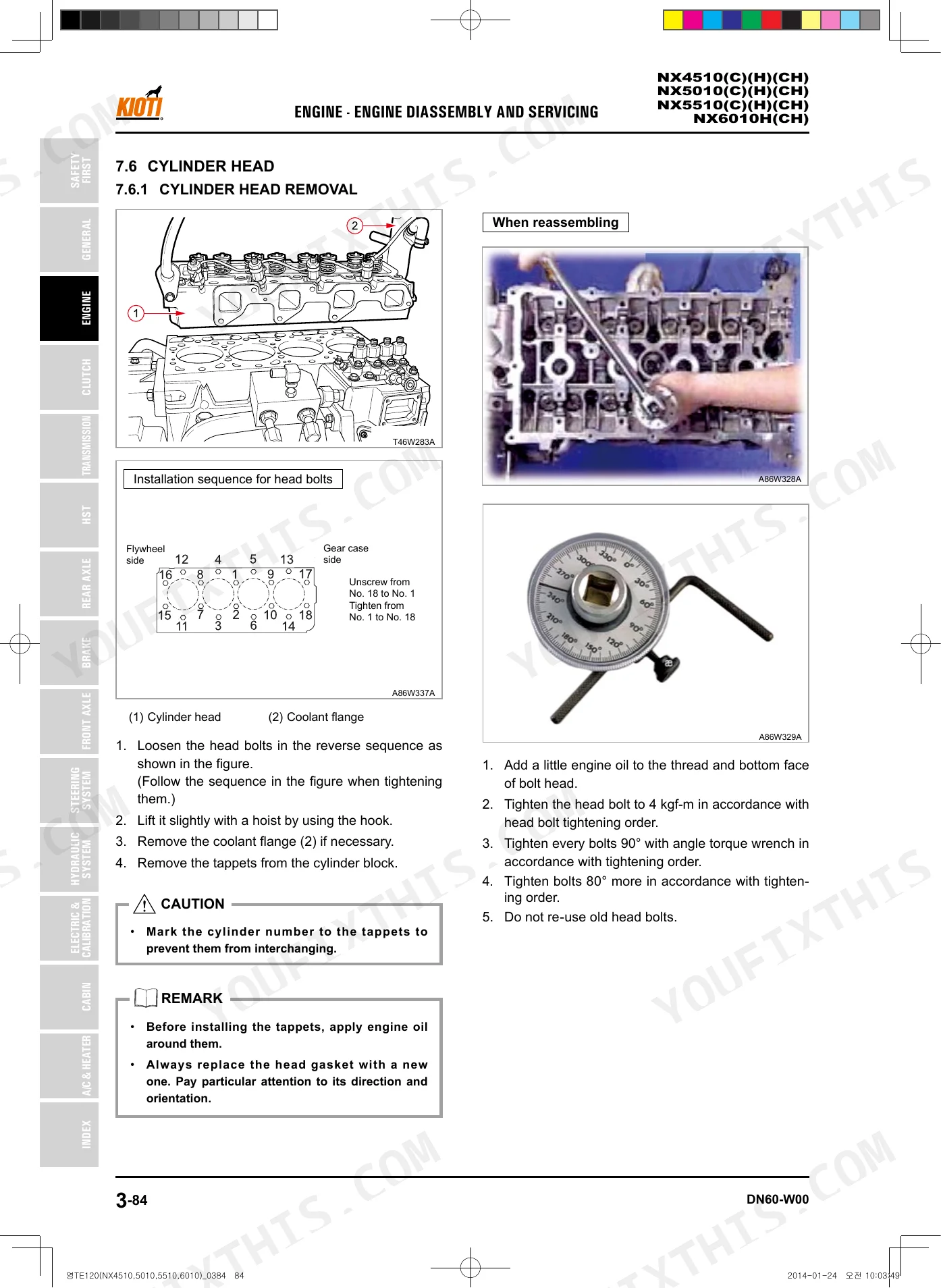
Measure the cold intake valve clearance and adjust to 0.25 mm (0.010 in.) ± 0.05 mm (0.002 in.) as shown on page 66. Torque the cylinder head bolts to 4.0 kgf-m (39.2 Nm, 28.8 lb-ft) following the first step sequence on page 70.
Manual Section: Engine Troubleshooting (4A220/4B243 models) p. 66Frequently Asked Questions
What do KIOTI NX series error codes mean?
The manual provides a comprehensive list of Diagnostic Trouble Codes (DTCs) and their corresponding descriptions and actions in Chapter 12, Section 9.5 "DTC (Diagnostic Trouble Code)", starting on page 12-239. For example, DTC P0001 with LB code 13 and lamp flash code 241 indicates an "IMV driver signal open circuit fault". p. 775
How do I clear an NX4510 hydraulic or transmission alarm?
The manual does not provide a general procedure to clear a hydraulic or transmission alarm. Instead, it lists specific troubleshooting steps for various problems in Chapter 5 "TRANSMISSION" (page 5-21) and Chapter 11 "HYDRAULIC SYSTEM" (page 11-37), which often involve identifying the cause and replacing or adjusting faulty components. For specific DTCs related to these systems, actions are provided in Chapter 12, Section 9.5.2 "Erorr code & action" (page 12-240), which may include "Clear the fault".
What are the torque specs for Kioti NX series wheel lugs, axle bolts, and loader mounts?
For rear wheel nuts (M16), the tightening torque is 196.1 ~ 225.6 Nm (20 ~ 23 kgf-m, 144.7 ~ 166.4 lb-ft). Front wheel bolts (M16) have the same torque. Rear axle case mounting bolts (M10) require 48 ~ 55.9 Nm (4.9 ~ 5.7 kgf-m, 35.4 ~ 41.2 lb-ft). The manual does not explicitly list "loader mounts" torque specifications, but "Axle case support (axle upper cover), center pin bracket (axle pivot pin)" is specified as 77.5 ~ 90.2 Nm (7.9 ~ 9.2 kgf-m, 57 ~ 66.5 lb-ft). p. 478
What are the replacement specifications for Hydraulic relief valve / relief-valve adjustment components?
The manual specifies the "Main relief pressure" for the hydraulic system as 185 kgf/cm² (18.13 MPa, 2,631 psi) and the "Relief valve pressure" for the HST system as 34.3 ±1.0 MPa (380 ± 10 kgf/cm², 5404 ± 142 psi). For the steering unit, the "Relief pressure" is 145 kgf/cm² (14.21 MPa, 2,062 psi), and if the measured value is out of standard, it suggests to "adjust the relief valve of the steering unit to the specification" (page 11-39). The manual implies replacement if the valve is faulty but does not provide specific replacement part numbers for adjustment components. p. 591
How quickly can I access this Kioti NX4510–NX6010 Series manual after buying?
Immediate download of the complete 1074-page searchable Shop Manual. Access it on any device — laptop at your desk or phone in the field.
Are there any print restrictions on this Kioti NX4510–NX6010 Series manual?
Yes, print as many copies as you want — there are no restrictions. Many mechanics print the section they need and bring it to the shop floor.
Are there hydraulic schematics in this Kioti NX4510–NX6010 Series manual?
Included. Hydraulic system schematics cover all circuits, control valves, and component specifications for the Kioti NX4510–NX6010 Series.


Reviews
There are no reviews yet.