


This 242-page Kubota B1700E, B2100E, B2400E Parts Catalog maps every component on your compact tractor, from crankcase fastener to ROPS bolt. Inside: exploded views for 95+ assemblies, full part numbers for the hydraulic pump and control valve, and cross-references spanning all three models in one book. Flip to the engine section for the crankcase, injection pump, governor, and nozzle holder. The hydraulic side breaks down the pump components, flow divider valve, steering controller, control valve, and cylinder case to the last O-ring. Rebuilding? Spec the +0.50mm oversize piston, the -0.20mm or -0.40mm undersize crankpin bearing set, or injection pump shims at 0.20mm or 0.25mm. No more squinting at faded dealer microfiche. Sections are bookmarked by assembly: tap, grab the number, order the part.
What's Inside This Kubota B1700E, B2100E, B2400E Parts Manual
| System | Pages |
|---|---|
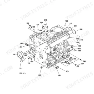
| Crankcase | 5-7 |
| Oil Pan | 8-10 |
| Cylinder Head | 11-12 |
| Gear Case | 13-14 |
| Head Cover | 15-16 |
| Main Bearing Case | 17-18 |
| Camshaft and Idle Gear Shaft | 19-20 |
| Piston and Crank Shaft | 21-22 |
| Flywheel | 23-24 |
| Fuel Camshaft and Governor Shaft | 25-26 |
| Stop Solenoid | 27-29 |
| Injection Pump | 30-31 |
| Governor | 32-34 |
| Speed Control Plate | 35-36 |
| Nozzle Holder and Glow Plug | 37-39 |
| Nozzle Holder [Component Parts] | 40-41 |
| Water Flange and Thermostat | 42-44 |
| Water Pump | 45-46 |
| Valve and Rocker Arm | 47-49 |
| Inlet Manifold | 50-51 |
| Exhaust Manifold | 52-53 |
| Upper Gasket Kit | 54-55 |
| Lower Gasket Kit | 56-59 |
| Dynamo | 60-61 |
| Dynamo [Component Parts] | 62-63 |
| Clutch | 64-65 |
| Hydraulic Pump | 66-67 |
| Hydraulic Pump [Component Parts] | 68-70 |
| Air Cleaner | 71-74 |
| Air Cleaner (Double) [Option] | 75-76 |
| Muffler | 77-78 |
| Accelerator Lever | 79-80 |
| Fuel Tank | 81-83 |
| Fuel Pipe | 84-87 |
| Fuel Filter [Component Parts] | 88-89 |
| Fan | 90-91 |
| Water Pipe | 92-93 |
| Radiator | 94-95 |
| Starter | 96-97 |
| Starter [Component Parts] | 98-99 |
| Battery | 100-101 |
| Panel Board | 102-104 |
| Panel Board [Component Parts] | 105-106 |
| Head Light | 107-108 |
| Tail Light/Hazard Light/Working Light | 109-110 |
| Electrical Wiring | 111-112 |
| Clutch Rod | 113-114 |
| Clutch Pedal | 115-117 |
| Clutch Housing | 118-120 |
| Frame | 121-122 |
| Transmission Case | 123-125 |
| Differential Gear Case | 126-127 |
| Rear Axle Case | 128-130 |
| Clutch Shaft/Propeller Shaft | 131-132 |
| 2nd Shaft/3rd Shaft/4th Shaft | 133-135 |
| 5th Shaft/PTO Shaft | 136-138 |
| Mid PTO | 139-140 |
| Rear Differential | 141-142 |
| Front Wheel Propeller Shaft | 143-144 |
| Main Gear Shift Fork | 145-147 |
| Rear Axle | 148-149 |
| Brake | 150-151 |
| Parking Brake Lever | 152-153 |
| Main Gear Shift Lever | 154-156 |
| Range Gear Shift Lever | 157-158 |
| Front Wheel Drive Lever | 159-160 |
| PTO Gear Shift Lever | 161-163 |
| Position Control Lever | 164-166 |
| Brake Pedal | 167-168 |
| Differential Lock Pedal | 169-170 |
| Front Axle Frame | 171-172 |
| Front Wheel Hub | 173-174 |
| Knuckle Arm | 175-176 |
| Steering Handle | 177-179 |
| Steering Controller | 180-182 |
| Steering Controller [Component Parts] | 183-189 |
| Hydraulic Oil Line (Suction) | 190-191 |
| Flow Divider Valve [Component Parts] | 192-193 |
| Hydraulic Oil Line (Steering) | 194-196 |
| Hydraulic Cylinder Case | 197-199 |
| Control Valve | 200-202 |
| Control Valve [Component Parts] | 203-206 |
| Lift Rod | 207-208 |
| Lower Link | 209-210 |
| Top Link | 211-212 |
| Front Grille | 213-214 |
| Hood (Bonnet) | 215-216 |
| Side Cover | 217-218 |
| Fender | 219-220 |
| Seat Support | 221-222 |
| Seat | 223-224 |
| Step | 225-227 |
| ROPS | 228-229 |
| Front Wheel (5.00-10) | 230-231 |
| Rear Wheel (8.3-16) | 232-233 |
| Rear Wheel (33*12.5-15) | 234-235 |
| Rear Wheel (31*15.5-15) | 236-237 |
| Label | 238-240 |
| Starter Relay Kit [Option] | 241-242 |
Quick Reference Specifications
| Specification | Value | Page |
|---|---|---|
| Piston Oversize | +0.50mm | p. 22 |
| Crankpin Metal Undersize (Option 1) | -0.20mm SET | p. 22 |
| Crankpin Metal Undersize (Option 2) | -0.40mm SET | p. 22 |
| Injection Pump Shim Thickness (Option 1) | 0.20mm | p. 31 |
| Injection Pump Shim Thickness (Option 2) | 0.25mm | p. 31 |
| Hazard Light Bulb Power Rating | 27W | p. 110 |
| Main Fuse Rating | 30A | p. 112 |
| Auto Fuse Rating (Accessory) | 5A | p. 112 |
| Auto Fuse Rating (Main) | 10A | p. 112 |
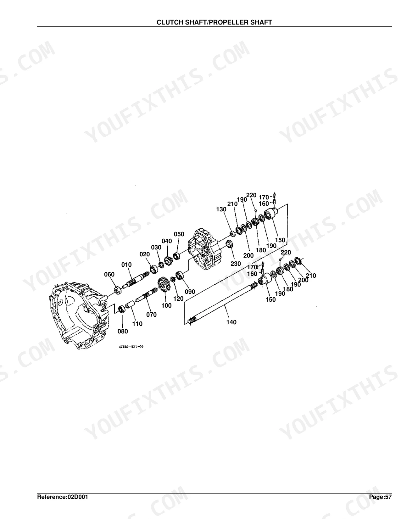
| Gear Clutch Shaft Teeth Count | 16T | p. 132 |
| Front Wheel Tire Size | 5.00-10 | p. 230 |
| Rear Wheel Tire Size | 8.3-16 | p. 232 |
Kubota B1700E, B2100E, B2400E Common Problems This Manual Covers
B1700E owners struggle to identify the correct 3-point hitch lift cylinder seal kit when rebuilding a drifting hitch p. 197
Open the Hydraulic Cylinder Case exploded view on page 197. Match the cylinder casting number on your tractor to the diagram callouts, then cross-reference seal and O-ring item numbers against the parts list. Confirm the kit covers piston seal, rod seal, and wiper before ordering.
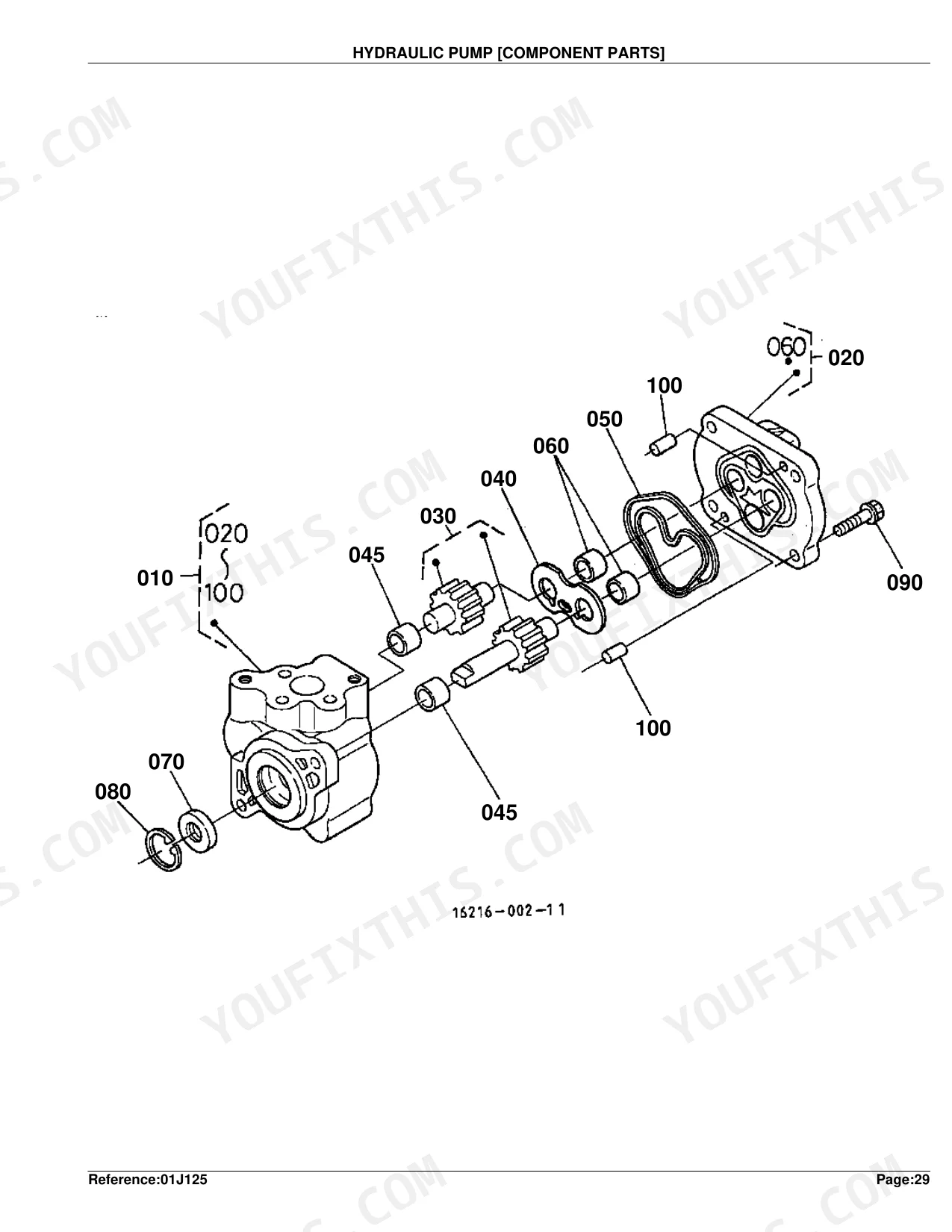
Manual Section: Hydraulic Cylinder CaseHydraulic pump rebuild components are needed, but the assembly drawing doesn't break out individual gear and shaft part numbers p. 68
Pull up the Hydraulic Pump Component Parts diagram on page 68. Each drive gear, driven gear, shaft, and gasket is called out individually with its own part number. Confirm your pump body casting matches the illustration, since early and late production runs use different internal gear sets.
Manual Section: Hydraulic Pump [Component Parts]A replacement starter solenoid arrives and doesn't match the unit on the tractor, so a component-level part number is needed p. 98
Reference the Starter Component Parts breakdown on page 98. Solenoid, brush holder, armature, and pinion are listed separately rather than as a complete starter assembly. Match the solenoid terminal layout in the exploded view to your unit before ordering, since the optional Starter Relay Kit on page 241 uses a different relay assembly.
Manual Section: Starter [Component Parts]Fuel filter housing leaks at the bowl and the correct gasket and bowl part numbers aren't obvious p. 88
Check the Fuel Filter Component Parts exploded view on page 88. Bowl, sealing ring, element, and retaining ring are itemized with individual part numbers. Cross-reference the Fuel Pipe section on page 84 if hose clamps or supply lines also need replacement, since those live in a separate parts table.
Manual Section: Fuel Filter [Component Parts]Brake shoes and drum hardware need replacing, but the parts list doesn't separate left and right side components p. 150
Turn to the Brake exploded view on page 150. Left and right shoe assemblies, return springs, anchor pins, and adjuster hardware are called out by item number with side-specific suffixes. Verify against the Brake Pedal linkage diagram on page 167 if the actuating rod, clevis pins, or return spring also show wear.
Manual Section: BrakeSteering controller leaks internally and a rebuild requires identifying every O-ring, seal, and spool component p. 183
See the Steering Controller Component Parts diagram on page 183, which spans seven pages of detailed exploded views. Every O-ring, backup ring, spool, sleeve, and centering spring is itemized individually. Cross-reference the Hydraulic Oil Line Steering section on page 194 if supply hoses or fittings also need replacement.
Manual Section: Steering Controller [Component Parts]Frequently Asked Questions
What are the replacement specifications for air filter?
For models with serial number up to 10266, the replacement air filter element is part number 67980-82630. From serial 10267 and up, use 6A100-82630. An optional double air cleaner is also available, with outer element 6C040-94240 and inner element 6C040-94250.
What are the replacement specifications for fuel filter?
Fuel filter element assembly is part number 15231-43560. For the complete fuel filter assembly with body and cup, order 15751-43010.
How quickly can I access this Kubota B1700E, B2100E, B2400E manual after buying?
Instant PDF download. The full 242-page searchable Parts Catalog is available immediately after payment. Open it on a laptop, tablet, or phone right in the shop.
Are there any print restrictions on this Kubota B1700E, B2100E, B2400E manual?
Yes, print as many copies as you want, with no restrictions. Many mechanics print just the section they need and carry it onto the shop floor.
Are hydraulic system diagrams in this Kubota B1700E, B2100E, B2400E manual?
This is a parts catalog, so it shows exploded parts diagrams rather than circuit schematics. It includes detailed exploded views of the hydraulic components — pump, control valve, cylinder, and oil lines — with OEM part numbers, not wiring-style circuit diagrams.
Document Quality
This is a scanned parts catalog, and you can search the full text thanks to an underlying OCR layer. The text in the parts lists is clear and easy to read, while the diagrams are raster images that show some pixelation when zoomed in. Labels and callout numbers on the illustrations are generally legible, though some are slightly fuzzy. The pages themselves are clean with minimal scan artifacts or skew.


Reviews
There are no reviews yet.