


This Kubota U17 Workshop Manual PDF (OEM #97899-61970) maps one machine family: the U17, U17-3, and U17-3α compact excavators, from the KICS digital control system to the undercarriage travel motors. Its 740 pages include hydraulic schematics for the full fluid circuit, wiring diagrams for the entire electrical system, and 200 pages of step-by-step disassembly and reassembly across every major assembly. Add 50 pages of torque specifications, 50 pages of exploded views, 20 pages of troubleshooting flowcharts, and a dedicated error code section for reading KICS fault displays. Torque the 1/4-inch hydraulic hose union nut to 24.5–29.4 N·m; fill the radiator to exactly 2.6 L. Those are factory numbers, not forum guesses. With your machine down, the bookmarked PDF opens on any device: search a keyword, find the spec, fix the machine.
What's Inside This Kubota U17, U17-3, U17-3α Manual
| System | Pages | Key Topics |
|---|---|---|
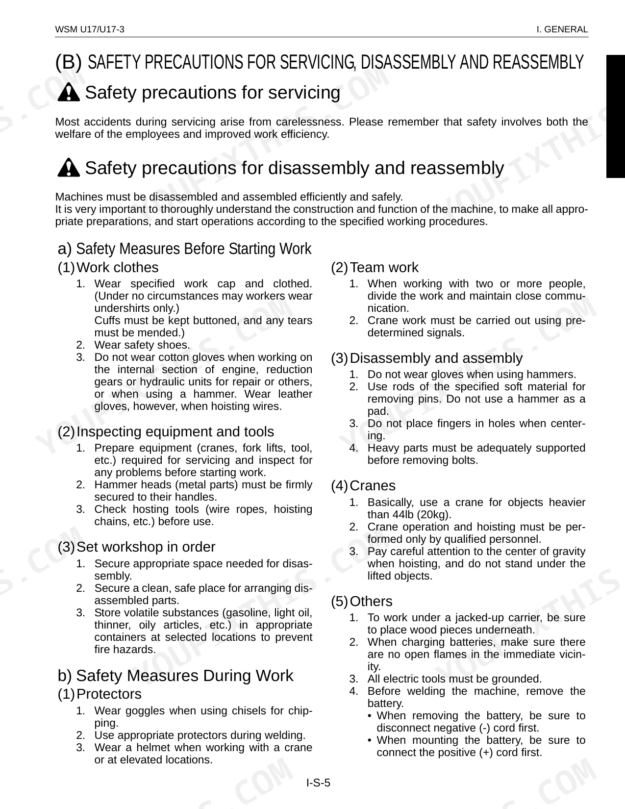
| I . General | 5-40 | Body and Engine Identification Marks, Safety Precautions for Servicing, Disassembly and Reassembly, Important Safety Process and Critical Functional Process |
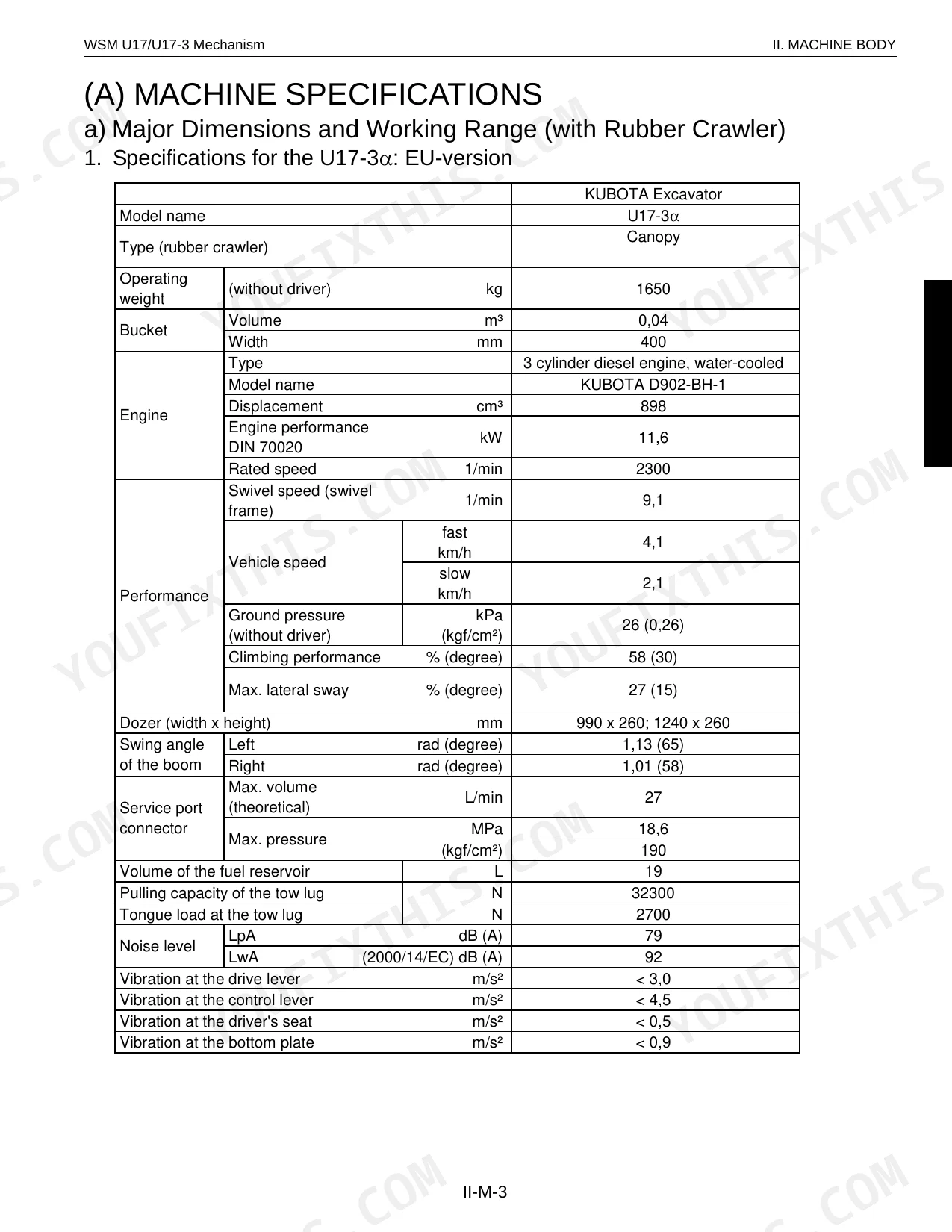
| II . MACHINE BODY (Mechanism Section) | 41-64 | MACHINE SPECIFICATIONS, MACHINE BODY STRUCTURE AND FUNCTION, Overall Arrangement, Under Carriage Components |
| II . MACHINE BODY (Service Section) | 65-132 | Specifications, Front Attachment, Upper Structure, Swivel Bearing, Travel Lever, Undercarrige |
| III . ENGINE (Mechanism Section) | 133-148 | ENGINE SPECIFICATIONS, NEW EMISSIONS CONTROL ENGINES, Outline, Engine List for Minor Change, Engine Features |
| III . ENGINE (Service Section) | 149-318 | ENGINE ACCESSORIES, Air Cleaner, Radiator, Thermostat, Muffler, Pump Coupling |
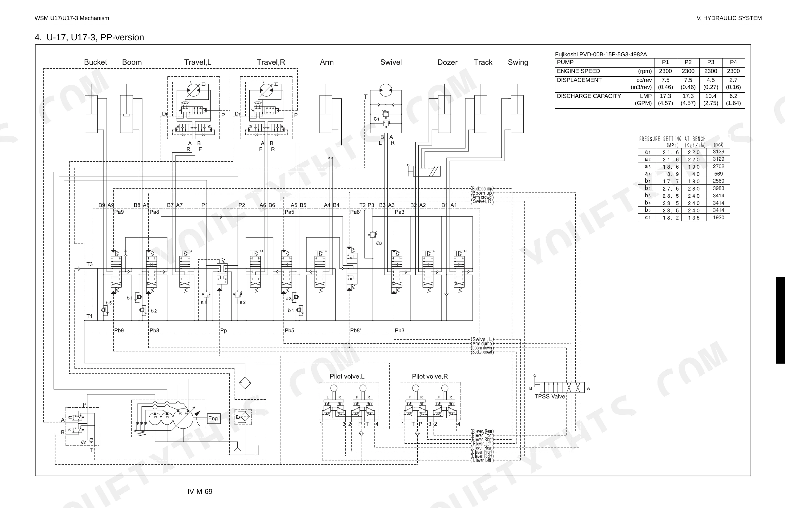
| IV . HYDRAULIC SYSTEM (Mechanism Section) | 319-390 | Main Pump, Control Valve, Swivel Motor, Travel Motor (Wheel Motor), Pilot Valve (Remote Control Valve), Hydraulic Circuit Diagram |
| IV . HYDRAULIC SYSTEM (Service Section) | 391-622 | Troubleshooting, Testing, Specifications, Disassembling and Reassembling, Pump, Control Valve |
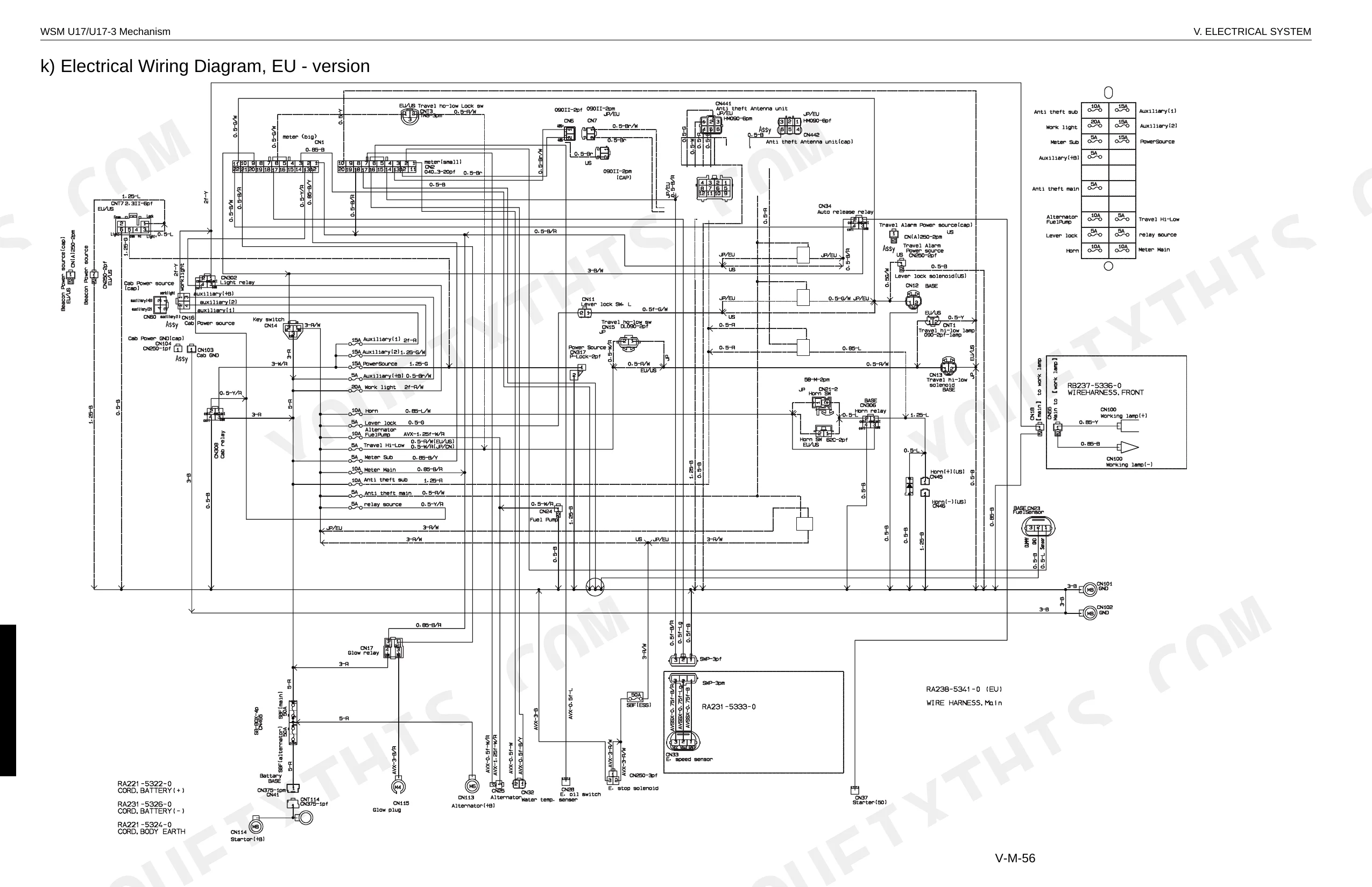
| V . ELECTRICAL SYSTEM (Mechanism Section) | 623-680 | GENERAL, KUBOTA INTELLIGENT CONTROL SYSTEM (KICS), Features of Digital Meter, Operating Mode, Servide Mode Menues, Electrical Component Layout |
| V . ELECTRICAL SYSTEM (Service Section) | 681-736 | Fuses, Battery, Horn, Glow Plug, Solenoid Valve, Fuel Pump |
| Conversion Tables | 737-740 | Length, Area, Volume, Flow amount, Force, Stress |
Quick Reference Specifications
| Specification | Value | Page |
|---|---|---|
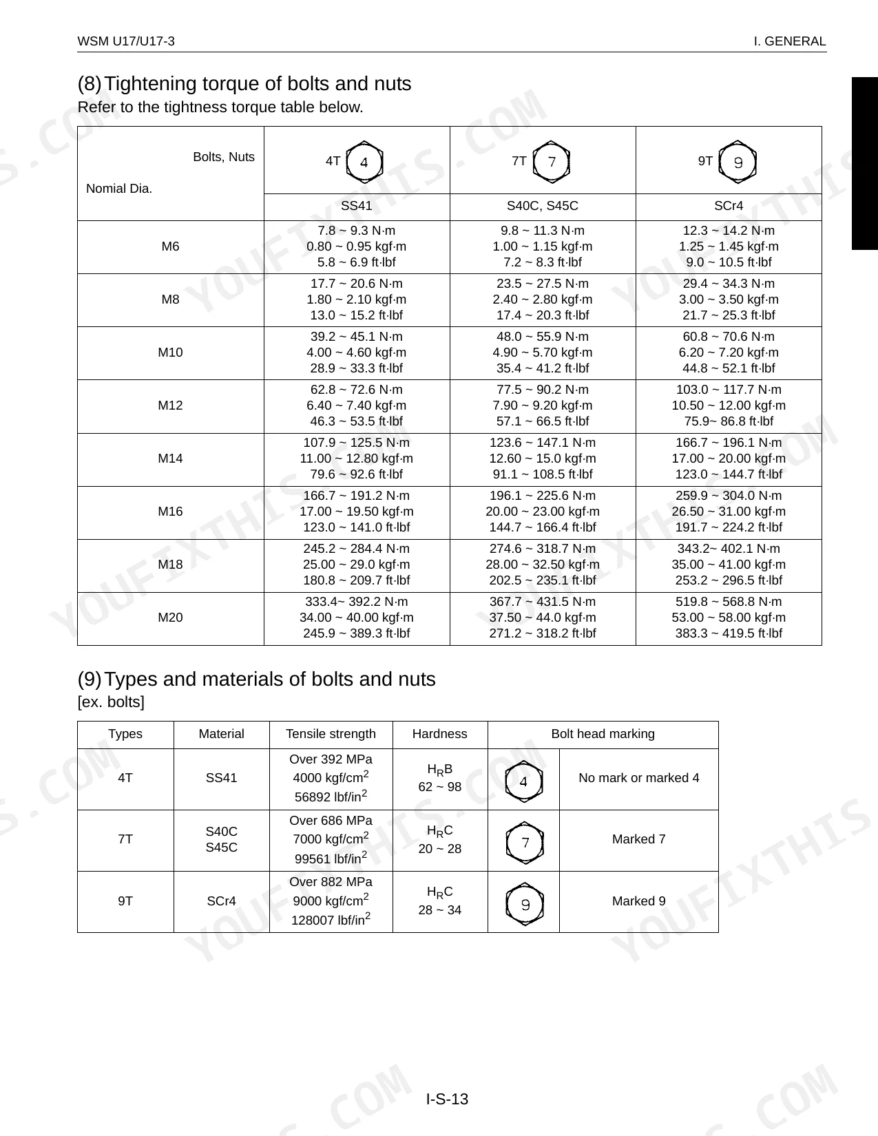
| Hose screw (Union nut section) 1/8" | 7.8 ~ 11.8 N·m | p. 15 |
| Hose screw (Union nut section) 1/4" | 24.5 ~ 29.4 N·m | p. 15 |
| Radiator soft water | 2.6 L | p. 77 |
| Reserve tank soft water | 0.56 L | p. 77 |
| Engine oil level check | daily | p. 19 |
| Hydraulic oil level check | daily | p. 19 |
| Engine Oil Capacity (at filter replacement) | 3.6 L | p. 77 |
| Total Hydraulic Oil Capacity | 21 L | p. 77 |
| Fuel Tank Capacity | 19 L | p. 77 |
| Radiator Soft Water Capacity | 2.6 L | p. 77 |
| Main Relief Valve Pressure (P1, P2) | 21.6 MPa | p. 47 |
| Main Relief Valve Pressure (P3) | 18.6 MPa | p. 47 |
Kubota U17, U17-3, U17-3α Common Problems This Manual Covers
Kubota U17 excavator bucket lifts slowly or stalls under load, arm won't extend fully p. 391
Check system pressure at the test port; main relief should read 21.6 MPa (page 47). If pressure is low, inspect pump flow per the hydraulic troubleshooting procedure starting on page 391. Verify hydraulic tank oil level meets the 13 L capacity spec; top off with correct grade before condemning the pump.
Manual Section: Hydraulic System General TroubleshootingEngine cranks slowly and won't start in cold weather, no-start despite recent glow plug replacement p. 713
Trace the glow plug circuit and relay function per the electrical component check on page 681. Test battery voltage; it should hold 12 V with 36 Ah capacity (page 713) under cranking load. Verify fuel level in the 19 L tank and inspect the water separator for water contamination before diagnosing the injection system.
Manual Section: Engine Electrical Components CheckHydraulic oil temperature climbs into warning range during extended work cycles, overheat alarm triggers p. 391
Inspect the radiator and oil cooler for debris blockage; clean fins thoroughly if airflow is restricted. Verify total hydraulic oil is at the correct 21 L system fill (page 77) and check for internal leakage at the control valve. Consult the hydraulic troubleshooting procedure starting on page 391 for pressure and flow diagnostics to isolate internal bypass.
Manual Section: Hydraulic System General TroubleshootingUpper structure hesitates and won't rotate smoothly when swiveling under full working load p. 438
Measure swivel speed; spec is 8.7 rpm (page 438). Check swivel reduction gear oil level and inspect swivel bearing grease condition. Verify main relief pressure is holding 21.6 MPa (page 47) before suspecting the swivel motor. Inspect the motor drain port for excessive internal leakage per the Swivel and Travel System Troubleshooting procedure.
Manual Section: Swivel & Travel System TroubleshootingEngine runs rough at idle with valve clatter and noticeably reduced digging power p. 244
Adjust valve clearance to 0.145 to 0.185 mm with the engine cold (page 244). Remove the valve cover and inspect all rocker arms and push rods for wear before setting clearances. Verify engine oil is filled to the 3.6 L capacity (page 77). If rough running continues after adjustment, proceed to the Engine Injection System Diagnosis section.
Manual Section: III . ENGINE (Service Section)Battery drains overnight and machine fails to start the following morning p. 713
Test battery voltage; it should measure 12 V with 36 Ah capacity (page 713) and hold under load. Check for parasitic current draw with the key off to identify a faulty relay or solenoid. Inspect all electrical cables and connections for corrosion per the annual service schedule on page 19. Clean terminals and confirm the alternator output before replacing the battery.
Manual Section: Engine Electrical Components CheckFrequently Asked Questions
What are the recommended service intervals?
Recommended service intervals vary by component and version. For the EU-version, daily checks include engine oil, hydraulic oil, fuel, and coolant levels. Lubricate the swivel gear every 50 hours, check nuts and bolts every 100 hours, and clean the air filter every 200 hours. For skilled personnel, check/adjust V-belt tension every 250 hours and change engine oil and oil filter every 500 hours.
What fluids and capacities does this machine require?
Several fluids with set capacities are needed. The radiator soft water capacity is 2.6 L (0.713 US gal) and the reserve tank holds 0.56 L (0.159 US gal). Crankcase engine oil at filter replacement is 3.6 L (0.295 US gal) of Class CF/CF-4 10W30. Hydraulic tank oil is 13 L (3.434 US gal) and total hydraulic oil is 21 L (5.812 US gal) of ISO VG 46. Wheel motor gear oil is 0.25 L (0.066 US gal) of SAE 90 (API, GL-4).
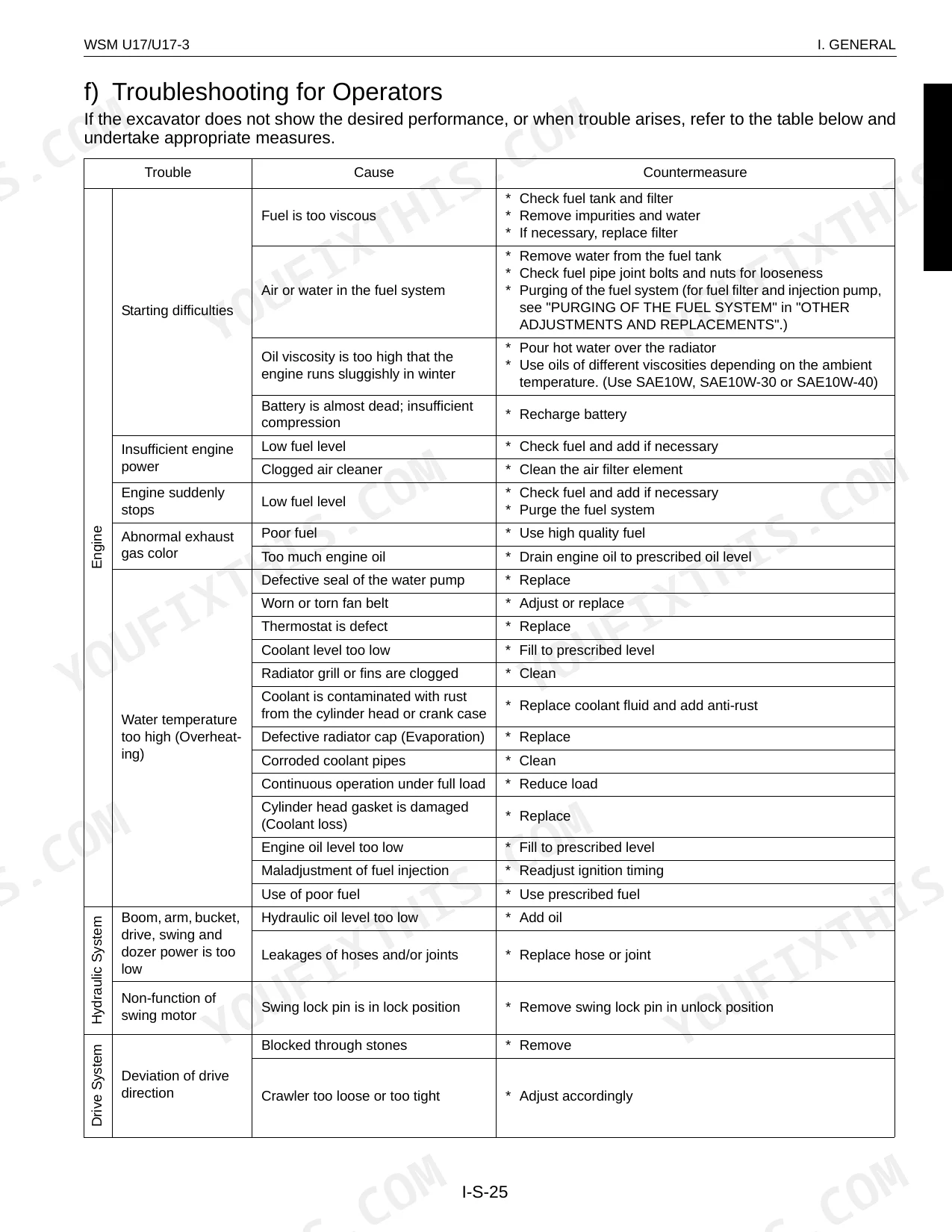
How to troubleshoot engine won't start?
If the engine does not start, check for no fuel, air in the fuel system, or water in the fuel system. Replenish fuel, bleed the system, or change fuel and repair the system as needed. Also, check for a clogged fuel hose or filter, incorrect injection timing, or a dead battery. If the battery is almost dead, recharge it.
What are the hydraulic system specifications?
The main pump (PVD-00B-14P-5G3-4552A) has a capacity of 7.5 x 2 cm³/rev for P1/P2 and a rated speed of 2300 min⁻¹. The main relief valve pressure for P1/P2 is 21.6 MPa (220 kgf/cm²). The swivel motor has a capacity of 195 cc/rev (11.9 in³/rev) and a brake pressure of 13.2 MPa (135 kgf/cm²). The travel motor has a displacement of 12.44 / 6.21 cm³/rev and a max pressure of 21.6 MPa (220 kgf/cm²).
Is this Kubota U17, U17-3, U17-3α Workshop Manual a digital download?
A 740-page Workshop Manual in searchable PDF format, available the moment you complete checkout. View on computer, tablet, or phone. No shipping wait.
Is this Kubota U17, U17-3, U17-3α Workshop Manual printable?
Yes. The PDF has no DRM restrictions, so print any page or section you need for your shop. Works with any standard printer.
Does this Kubota U17, U17-3, U17-3α manual include wiring diagrams?
Yes. Full electrical schematics are included with wire colors, connector locations, and circuit descriptions.
Document Quality
This document is a scanned PDF with an OCR layer, allowing you to search and copy text throughout. The text is generally crisp and easy to read, with no noticeable blurriness or fading. Diagrams and illustrations are a mix of sharp, vector-like drawings with clear labels and raster images (photos) that are also sufficiently clear for identification. Pages are clean with no significant scan artifacts, stains, or skewed content, though some blank filler pages are present.

Reviews
There are no reviews yet.