

Part of the Kubota Repair Manuals.
This Kubota Shop Manual covers the ZD221-48 and ZD221-54 zero-turn mowers powered by the D782-E3-ZD-1 diesel engine. It runs 262 pages with a searchable text layer, so you can find a procedure quickly.
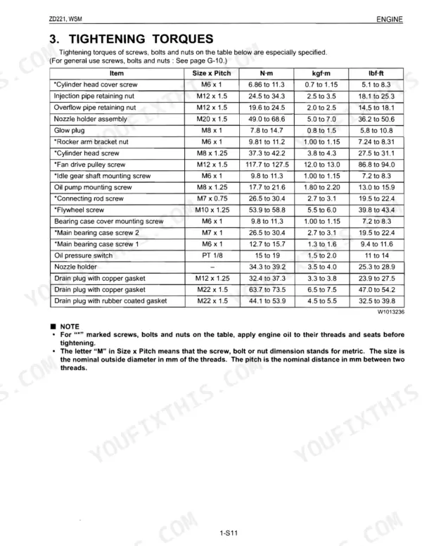
Coverage is organized by system: General information, the Engine, the Transaxle with its hydrostatic transmission, the Front Axle, the Hydraulic system, the Electrical system with wiring diagrams, and the Mower deck. Each system carries its own servicing specifications and tightening torques.
Owners and independent shops can use it to set valve clearance, rebuild the hydrostatic transaxle, trace starting and charging faults, service the lift hydraulics, and level or rebuild the RCK mower deck. It is delivered as a downloadable PDF you can view on a phone, tablet or computer, or print the exact pages you need for the job.
What's Inside This Manual
| System | Pages | Key Topics |
|---|---|---|
| General | 13-70 | Identification, Cylinder Nymber, Handling Precautions for Electrical Parts and Wiring (Battery, Fuse, Connector, Handling of Circuit Tester), Lubricants, Fuel and Coolant |
| Sect 1 Engine | 71-130 | Engine Body, Lubricating System, Cooling System, Fuel System, Separating Engine, Cylinder Head and Valve, Gear Case and Timing Gears, Piston and Connecting Rod |
| Sect 2 Transaxle | 131-174 | Travelling System (Hydrostatic Transmission, Structure, Pump and Motor, Check Valve and High Pressure Relief Valve, Oil Flow, Power Trains Operation, Control Linkage, Final Reduction Gear Section, PTO System) |
| Sect 3 Front Axle | 175-184 | Structure, Disassembling and Servicing (Disassembling and Assembling, Separating Front Wheel and Wheel Bracket) |
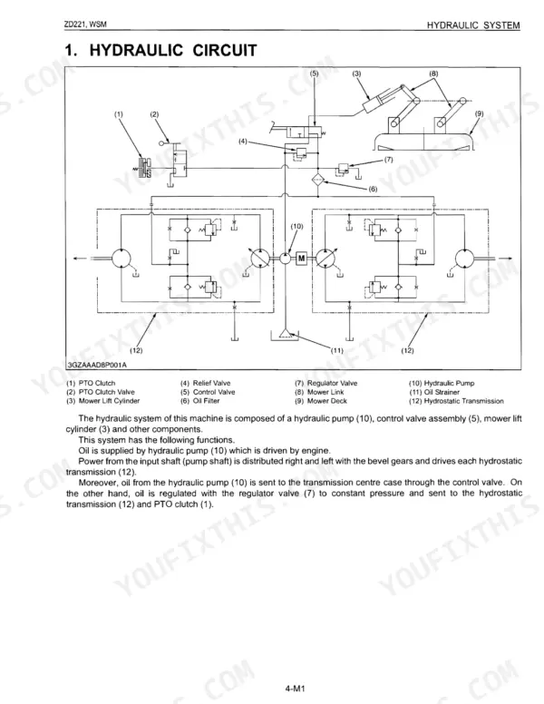
| Sect 4 Hydraulic | 185-202 | Hydraulic Circuit, Hydraulic Pump, Hydraulic Control Valve and Valve Adaptor, Lift Cylinder, Mower Linkage, Servicing Specifications |
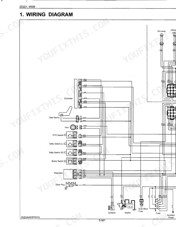
| Sect 5 Electrical | 203-240 | Wiring Diagram, Starting System (Relay, Starter, Glow Plug, Safety Switch, Fuel Pump, Engine Stop Solenoid), Charging System (AC Dynamo, Regulator, Easy Checker) |
| Sect 6 Mower | 241-262 | Disassembling and Assembling (Checking and Adjusting, Rck48S, Rck48P and Rck54P, Servicing), Structure (Power Transmission, Lifting Mechanism), Servicing Specifications |
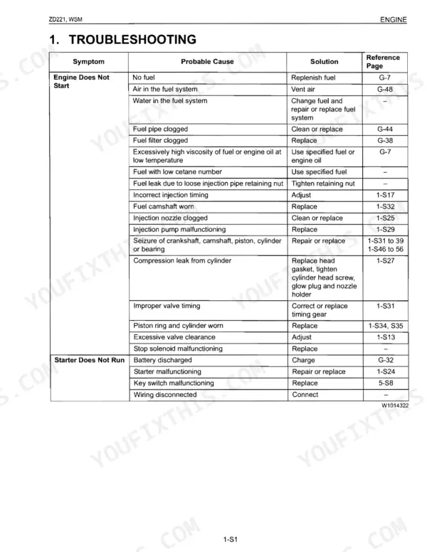
Every system also includes tightening torques, checking, and troubleshooting.
Quick Reference Specifications
| Specification | Value | Page |
|---|---|---|
| General Use Screws, Bolts and Nuts (M8, No-grade or 4T, Ordinariness) | 18 to 20 N·m (1.8 to 2.1 kgf·m, 13 to 15 lbf·ft) | p. 24 |
| General Use Screws, Bolts and Nuts (M10, No-grade or 4T, Ordinariness) | 40 to 45 N·m (4.0 to 4.6 kgf·m, 29 to 33 lbf·ft) | p. 24 |
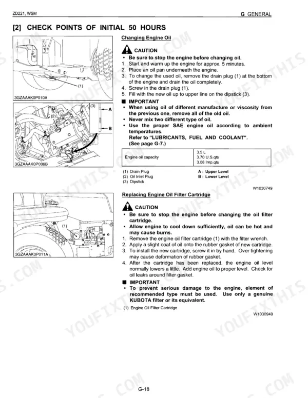
| Engine crankcase (with filter) capacity | 3.5 L | p. 10 |
| Fuel tank capacity | 23 L | p. 10 |
| Transmission including rear axle gear case capacity | 7.5 L | p. 10 |
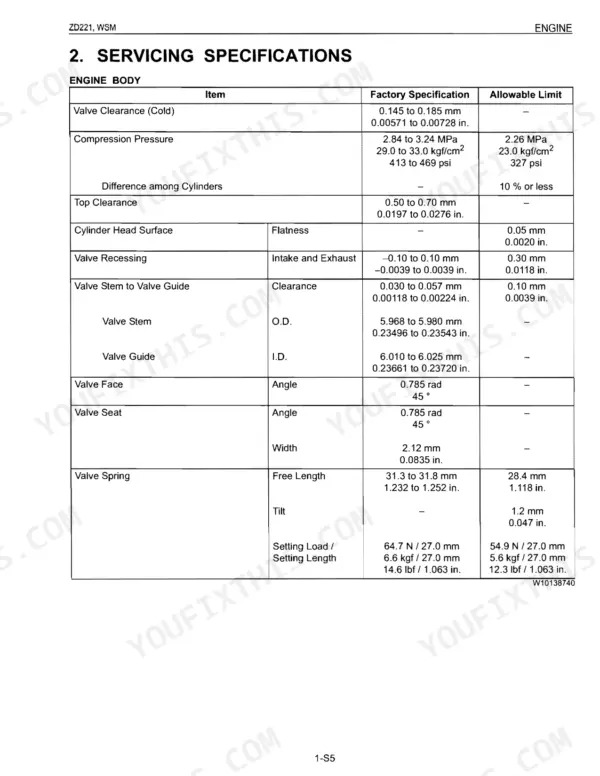
| Engine Valve Clearance (Cold) | 0.145 to 0.185 mm | p. 77 |
| Engine Compression Pressure (Factory Spec) | 2.84 to 3.24 MPa | p. 77 |
| Fan Belt Tension (deflection) | 7.0 to 9.0 mm | p. 81 |
| Cylinder head cover screw torque (M6 x 1) | 6.86 to 11.3 N·m | p. 83 |
| Rear wheel mounting nut torque | 65 to 75 N·m | p. 150 |
| Relief Valve (Control Valve) Setting Pressure | 3.0 to 3.5 MPa | p. 198 |
| Mower blade screw torque | 103 to 117 N·m | p. 249 |