

This Kubota Workshop Manual covers the U17, U17-3 and U17-3α compact excavators, publication number 97899-61970, built around the D902-BH-1 and D902-E3-BH-2 diesel engines. It is a 740 page manual with a searchable text layer.
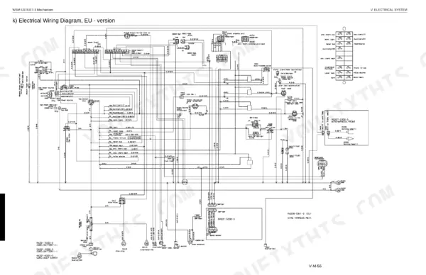
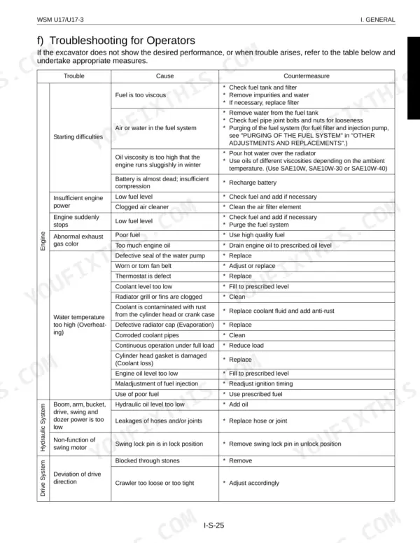
The manual is organized into General, Machine Body, Engine, Hydraulic System and Electrical System, each split into a mechanism section that explains how the system works and a service section with troubleshooting, testing, specifications, and disassembly and reassembly steps. It also covers the Kubota Intelligent Control System (KICS) and the digital meter.
With this PDF you can diagnose hydraulic and electrical faults, rebuild the pump or control valve, service the engine, and set up the undercarriage correctly, using the manual's own torque tables and service limits. Download it once and read it on any device, or print the pages you need at the bench.
Complete the set for your U17, U17-3, U17-3α
- Operator Manual: Kubota U17-3 Operator Manual
What's Inside This Manual
| System | Pages | Key Topics |
|---|---|---|
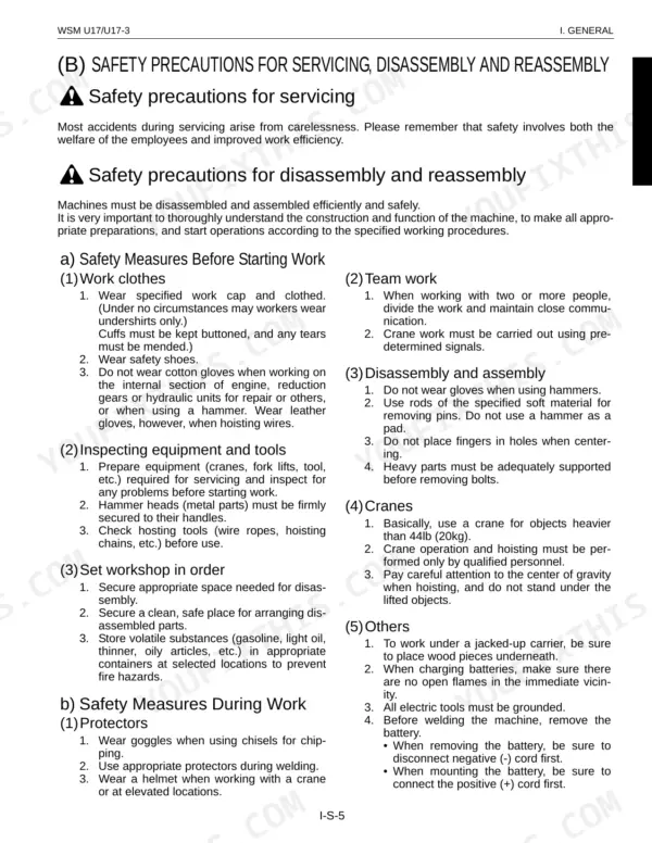
| I . General | 5-40 | Body and Engine Identification Marks, Safety Precautions for Servicing, Disassembly and Reassembly, Important Safety Process and Critical Functional Process |
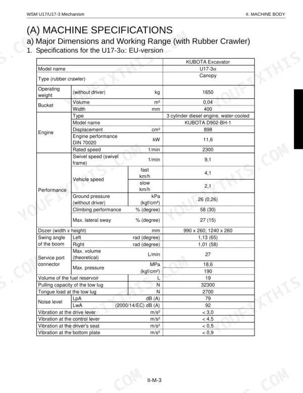
| Ii . Machine Body (Mechanism Section) | 41-64 | Machine Specifications, Machine Body Structure and Function, Overall Arrangement, Under Carriage Components |
| Ii . Machine Body (Service Section) | 65-132 | Specifications, Front Attachment, Upper Structure, Swivel Bearing, Travel Lever, Undercarrige |
| Iii . Engine (Mechanism Section) | 133-148 | Engine Specifications, New Emissions Control Engines, Outline, Engine List for Minor Change, Engine Features |
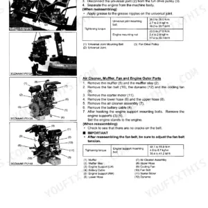
| Iii . Engine (Service Section) | 149-318 | Engine Accessories, Air Cleaner, Radiator, Thermostat, Muffler, Pump Coupling |
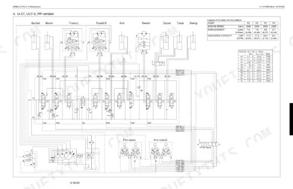
| Iv . Hydraulic System (Mechanism Section) | 319-390 | Main Pump, Control Valve, Swivel Motor, Travel Motor (Wheel Motor), Pilot Valve (Remote Control Valve), Hydraulic Circuit Diagram |
| Iv . Hydraulic System (Service Section) | 391-622 | Troubleshooting, Testing, Specifications, Disassembling and Reassembling, Pump, Control Valve |
| V . Electrical System (Mechanism Section) | 623-680 | General, Kubota Intelligent Control System (Kics), Features of Digital Meter, Operating Mode, Servide Mode Menues, Electrical Component Layout |
| V . Electrical System (Service Section) | 681-736 | Fuses, Battery, Horn, Glow Plug, Solenoid Valve, Fuel Pump |
| Conversion Tables | 737-740 |
Quick Reference Specifications
| Specification | Value | Page |
|---|---|---|
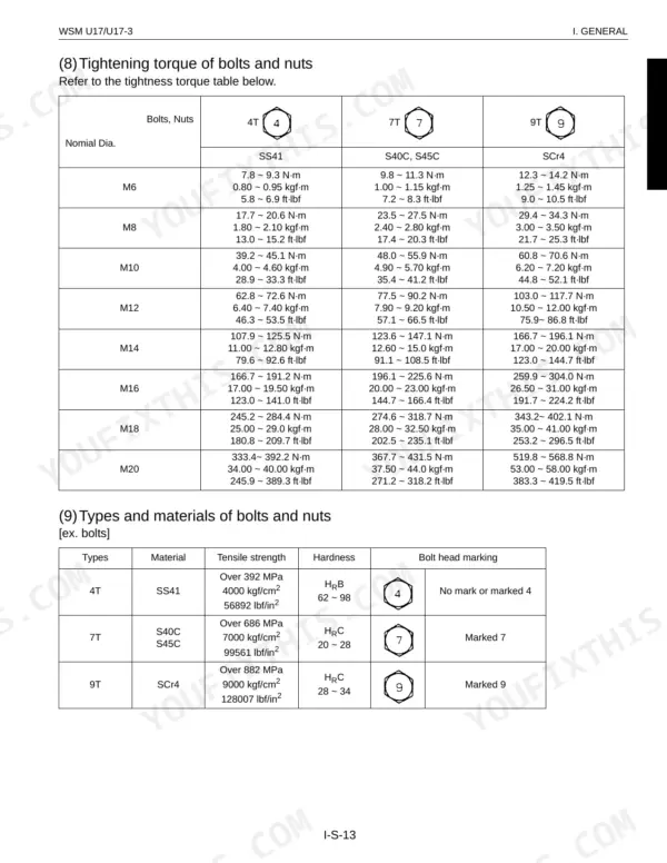
| Hose screw (Union nut section) 1/8" | 7.8 ~ 11.8 N·m | p. 15 |
| Hose screw (Union nut section) 1/4" | 24.5 ~ 29.4 N·m | p. 15 |
| Radiator soft water | 2.6 L | p. 77 |
| Reserve tank soft water | 0.56 L | p. 77 |
| Engine oil level check | daily | p. 19 |
| Hydraulic oil level check | daily | p. 19 |
| Engine Oil Capacity (at filter replacement) | 3.6 L | p. 77 |
| Total Hydraulic Oil Capacity | 21 L | p. 77 |
| Fuel Tank Capacity | 19 L | p. 77 |
| Radiator Soft Water Capacity | 2.6 L | p. 77 |
| Main Relief Valve Pressure (P1, P2) | 21.6 MPa | p. 47 |
| Main Relief Valve Pressure (P3) | 18.6 MPa | p. 47 |