


This is the Mitsubishi D04FD-TAA Service Manual, 252 pages of factory overhaul procedures for the 4.249 L electronically controlled diesel engine, OEM publication 99616-H0100.It covers the engine from end to end: outline drawings and system flows, full service data and tightening torque tables, special tools, and step-by-step disassembly, inspection, repair and reassembly of the cylinder head, valve mechanism, pistons and connecting rods. Dedicated sections handle the fuel, lubrication, cooling, and inlet and exhaust systems, the electrical system with starter and alternator, engine adjustment and break-in, and a large electronic troubleshooting section covering the ECM, diagnostic codes and connector terminals.With it you can set valve clearances, torque the cylinder head and rod bolts correctly, bleed the fuel system, and work through diagnostic codes rather than swapping parts. Delivered as a downloadable PDF for any device or printing.
What's Inside This Mitsubishi D04FD-TAA Manual
| System | Pages | Key Topics |
|---|---|---|
| Introduction | 3-15 | How to Use This Manual, Terms Used in This Manual, Abbreviations, Units of Measurement, Safety Cautions, About Warning Labels |
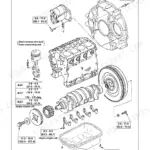
| General | 16-28 | Outline Drawings (D04FD-Taa Outline Drawings), System Flow (Fuel Flow, Oil Flow, Cooling Water Flow, Inlet and Exhaust Flow, Electrical Wiring Diagram) |
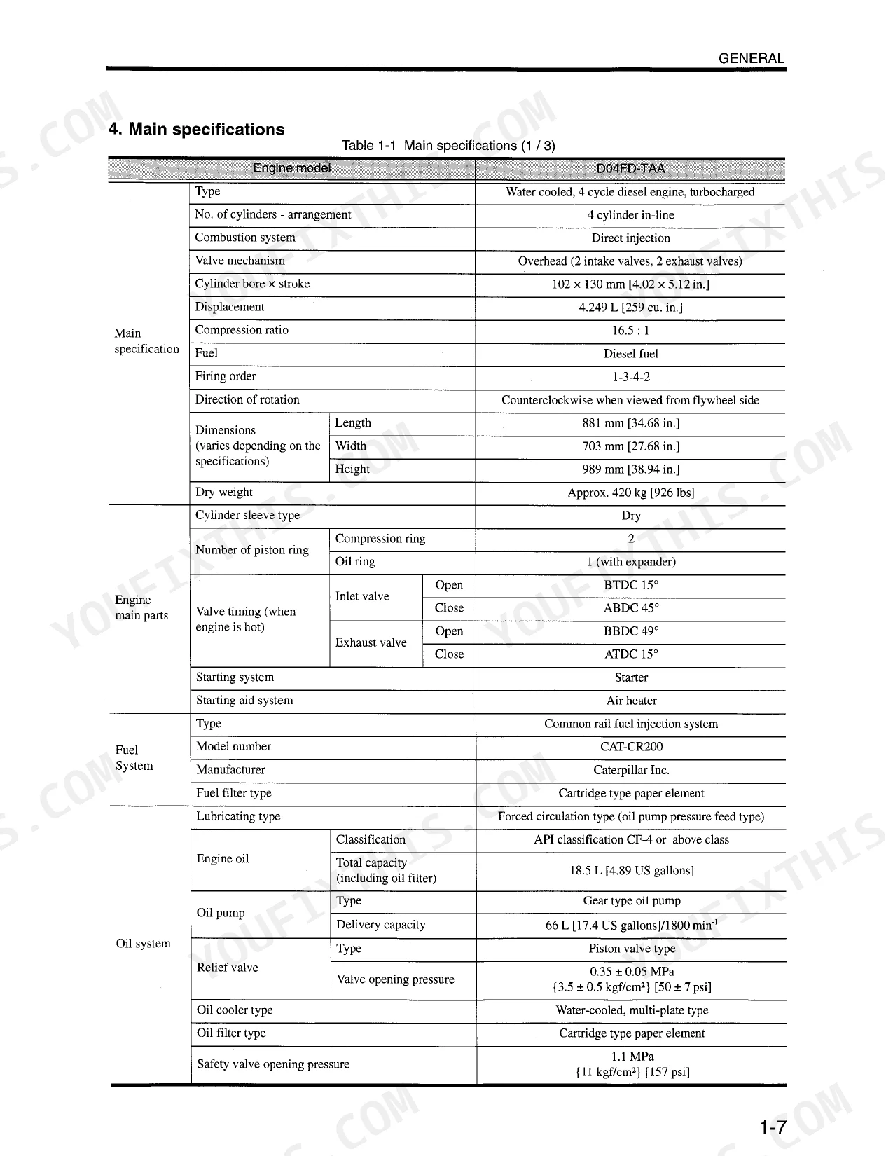
| Service Data | 29-41 | Maintenance Service Data (Engine General, Engine Main Part, Lubrication System, Cooling System, Inlet and Exhaust System, Electrical System) |
| Basic and Special Tools | 42-46 | Special Tools |
| Overhaul Instructions | 47-49 | Determining Overhaul Timing |
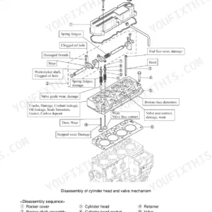
| Disassembling Engine Main Parts | 50-62 | Disassembling and Inspecting Cylinder Head and Valve Mechanism (Removing Harness, Removing Injector, Removing Rocker Case, Removing Rocker Shaft Assembly, Disassembling Rocker Shaft Assembly, Removing Valve Bridge, Removing Cylinder Head Bolt, Removing Cylinder Head Assembly, Removing Valves and Valve Springs, Removing Valve Stem Seal, Bridge Guide, Installing Bridge Guide) |
| Inspecting and Repairing Engine Main Parts | 63-89 | Inspecting and Repairing Cylinder Head and Valve Mechanism (Measuring Clearance Between Rocker Bushing and Rocker Shaft, Replacing Rocker Bushing, Measuring Valve Stem Outside Diameter and Valve Guide Inside Diameter, Replacing Valve Guide, Inspecting Valve Face, Refacing Valve Face, Refacing Valve Seat, Replacing Valve Seat, Lapping Valve and Valve Seat, Measuring Perpendicularity and Free Length of Valve Spring, Measuring Distortion of Cylinder Head Bottom Face, Measuring Pushrod Runout) |
| Reassembling Engine Main Parts | 90-98 | Reassembling Piston, Connecting Rod |
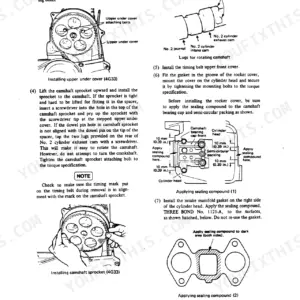
| Fuel System | 99-107 | Reassembling Timing Gear and Camshaft (Installing: Front Plate, Tappet) |
| Lubrication System | 108-117 | Removing and Inspecting Lubrication System, Disassembling |
| Cooling System | 118-127 | Removing Cooling System, Disassembling |
| Inlet and Exhaust System | 128-133 | Removing Inlet and Exhaust Sysytem (Inlet System, Exhaust System), Disassembling, Inspecting and Reassembling Inlet and Exhaust System (Measuring Exhaust Manifold Distortion) |
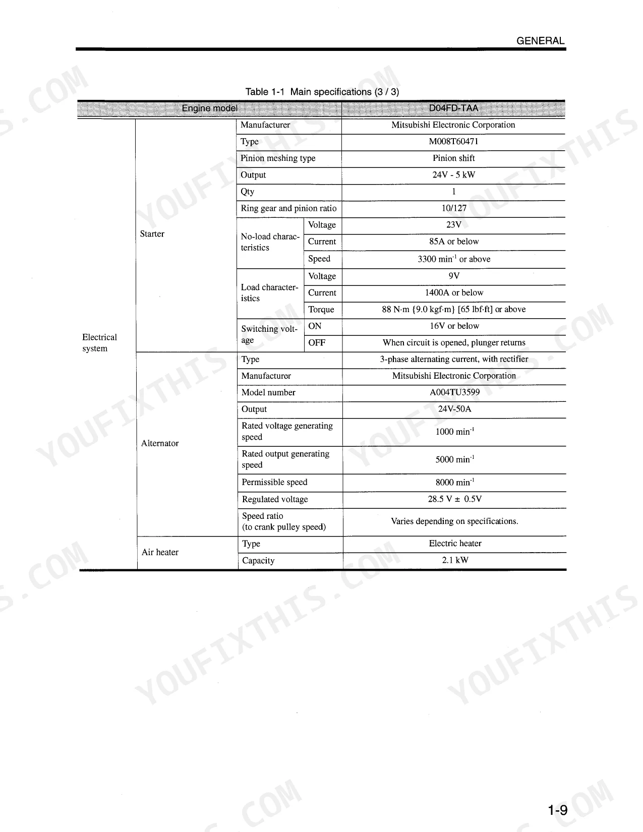
| Electrical System | 134-159 | Removing Electrical System (Removing Starter, Inspection Before Removing Alternator, Removing Alternator), Disassembling |
| Engine Adjustment, Break-In Operation and Performance Test | 160-167 | Engine (Inspecting and Adjusting Valve Clearance, Bleeding Fuel System) |
| Troubleshooting | 168-252 | Electronic Troubleshooting (System Overview, Engine Speed Governor, Timing Considerations, Fuel Injection, Diagnostic, Event, Programmable Parameters, Passwords, Replacing the Ecm, Self-Diagnostics, Diagnostic Code, Ecm Harness Connector Terminals, Harness Connector Terminal Removal, Harness Connector Terminal Insertion) |
Quick Reference Specifications
| Specification | Value | Page |
|---|---|---|
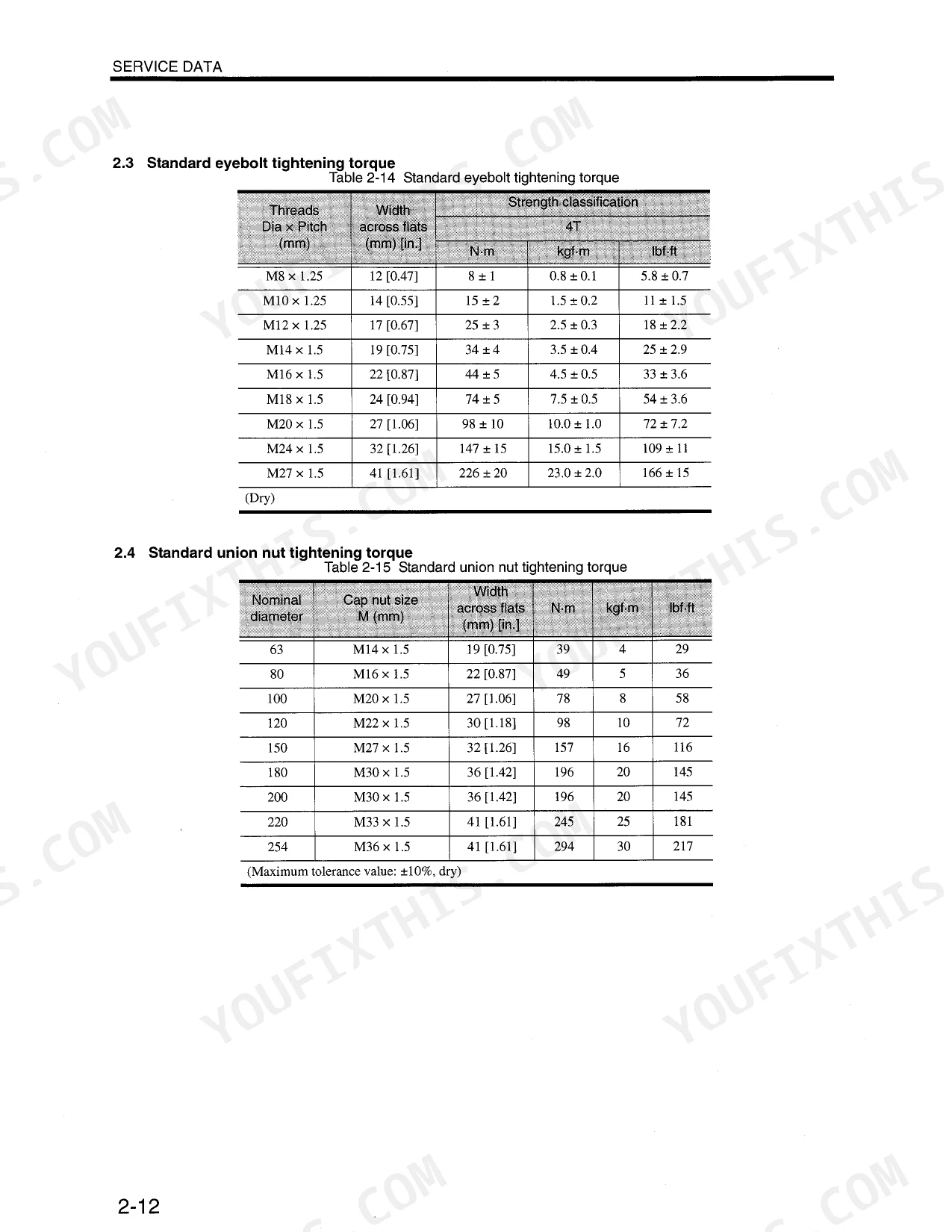
| Fuel pump mounting eye bolt torque | 34 ± 4 N·m {3.4 ± 0.4 kgf·m} [24.6 ± 2.9 lbf·ft] | p. 37 |
| Fuel filter mounting eye bolt torque | 34 ± 4 N·m {3.4 ± 0.4 kgf·m} [24.6 ± 2.9 lbf·ft] | p. 37 |
| Air vent plug tightening torque (on fuel filter) | 9.8 ± 2.0 N·m {1.0 ± 0.2 kgf·m} [7.2 ± 1.5 lbf·ft] | p. 104 |
| Nozzle gland torque | 29.4 ± 2.9 N·m {3.0 ± 0.3 kgf·m} [22 ± 2.2 lbf·ft] | p. 37 |
| Fuel pump gear nut torque | 90 ± 6 N·m {9.2 ± 0.6 kgf·m} [66.4 ± 4.4 lbf·ft] | p. 37 |
| Thermostat valve opening temperature | 71 ± 2°C [160 ± 3.6°F] | p. 35 |
| Thermostat temperature at which valve lift becomes 10 mm [0.39 in.] or above | 85°C [185°F] | p. 35 |
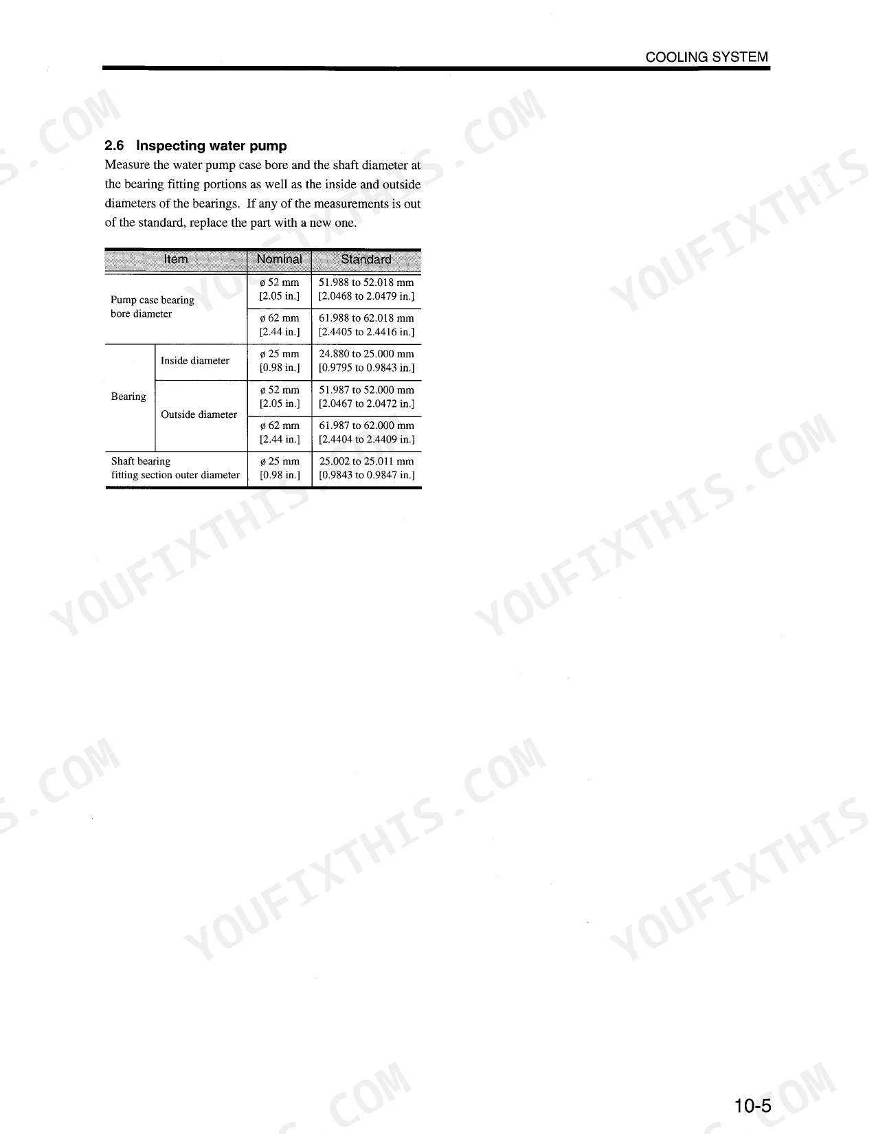
| Water pump inside diameter of pump case bearing fitting portion | 51.988 to 52.018 mm [2.0468 to 2.0479 in.] | p. 35 |
| Water pump bearing inside diameter | 51.987 to 52.000 mm [2.0467 to 2.0472 in.] | p. 35 |
| Oil filter tightening torque | 49 ± 4.9 N·m {5.0 ± 0.5 kgf·m} [36.2 ± 3.6 lbf·ft] | p. 116 |
| Oil filter replacement interval | Every 500 hrs | p. 109 |
| Speed/timing sensor (crankshaft side) torque | 1.7 ± 1.7 N·m {1.65 ± 0.15 kgf·m} [11.9 ± 1.1 lbf·ft] | p. 38 |
Mitsubishi D04FD-TAA Common Problems This Manual Covers
Hard start or no-start after sitting
Air ingress, a clogged fuel filter, a weak transfer pump or worn injectors leave this diesel hard to start after it sits. The fuel system section covers inspection, repair and bleeding.
Manual Section: Fuel System p. 99Loss of power under load
A restricted air intake or exhaust starves the engine and drops power under load. This section covers removing, inspecting and reassembling the inlet and exhaust system, including manifold checks.
Manual Section: Inlet and Exhaust System p. 128Overheating or coolant shutdown
Coolant loss, a stuck thermostat or a worn water pump can push temperatures to the ECM trip level and shut the engine down. The cooling section covers thermostat and water pump service.
Manual Section: Cooling System p. 118Low oil pressure warning
A degraded oil pressure warning or accelerated wear points to low or worn oil, or a tired oil pump. The lubrication section covers removing, inspecting and reassembling those components.
Manual Section: Lubrication System p. 108Fault codes or unstable speed control
Because this engine runs an ECM, drivability and governor faults show up as diagnostic codes. The troubleshooting section covers the electronic governor, self-diagnostics, diagnostic codes and ECM replacement.
Manual Section: Troubleshooting p. 168Rough idle or noisy valvetrain
Incorrect valve clearance leaves the engine rough at idle and noisy up top. The adjustment section gives the cold inlet and exhaust clearances and the procedure to reset them.
Manual Section: Engine Adjustment, Break-in Operation and Performance Test p. 160Cylinder head or valve wear
Compression loss and burnt or worn valves eventually call for head work. The inspection and repair section covers valve guide, seat and face service plus cylinder head flatness checks.
Manual Section: Inspecting and Repairing Engine Main Parts p. 63Frequently Asked Questions
Which engine does this manual cover?
It covers the Mitsubishi D04FD-TAA diesel engine, a 4.249 L four-cylinder unit with a 16.5 to 1 compression ratio, under OEM publication 99616-H0100.
Does it include torque specifications?
Yes. The Service Data section lists the tightening torque tables, for example the cylinder head bolt torque at 137 plus or minus 5 N and the connecting rod cap bolt at 103 plus or minus 5 N. p. 29
Does it cover electronic diagnostics and fault codes?
Yes. The Troubleshooting section covers electronic diagnostics in detail, including diagnostic codes, self-diagnostics, programmable parameters and ECM replacement. p. 168
Does it cover cooling system service?
Yes. The Cooling System section covers removing, disassembling and inspecting the cooling components, including the thermostat and water pump. p. 118
What format is this manual in?
Delivered as a 252-page searchable PDF, with an instant download after checkout. Open it on a laptop, tablet, or phone and bring it straight to the shop floor.
Are there any print restrictions on this manual?
Absolutely. No DRM or copy protection. Print the whole manual or just the pages you need. Any home or office printer works.
Are electrical wiring diagrams included in this Mitsubishi D04FD-TAA manual?
Included. The Mitsubishi D04FD-TAA Service Manual covers complete wiring harness diagrams, electrical circuits, and connector pinouts.


Reviews
There are no reviews yet.