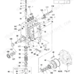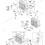
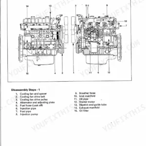
Part of the Isuzu 4BG1, Isuzu 6BG1 engine documentation.
This is the Isuzu Workshop Manual (publication IDE-2370) for the BG1-family industrial diesel engines, covering the AA-4BG1T, AA-6BG1, BB-4BG1T and BB-6BG1T models built from 1999. Its 220 pages take you from maintenance through full engine disassembly, inspection and repair, and reassembly, with the AA-4BG1T and BB-4BG1T being the turbocharged versions.
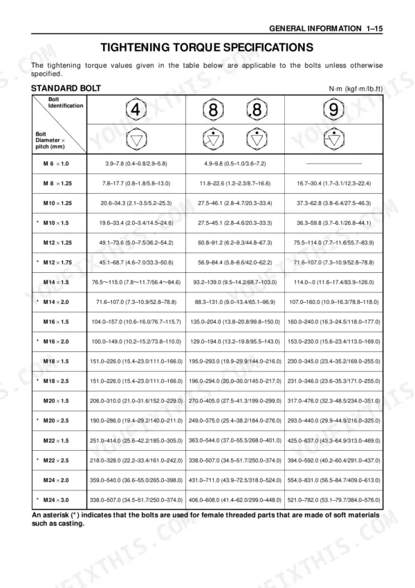
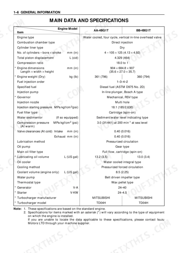
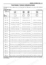
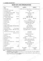
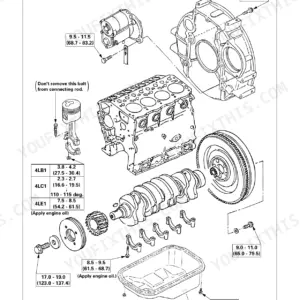
System chapters cover the lubricating, cooling and fuel systems, the turbocharger, the air compressor and the engine electricals, followed by troubleshooting and a detailed repair standards section. Key data is here too, including cold valve clearance of 0.40 mm, injection starting pressure of 18.1 MPa and torque figures for the cylinder head, connecting rods, flywheel and main bearing caps.
For anyone maintaining or rebuilding one of these four-cylinder and six-cylinder Isuzu industrial engines, this PDF supplies the factory procedures, service limits and settings needed to do the work properly.
What's Inside This Manual
| System | Pages | Key Topics |
|---|---|---|
| Maintenance | 28-47 | Lubricating System, Fuel System, Cooling System, Injection Timing |
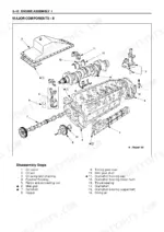
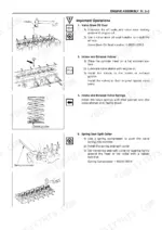
| Engine Assembly I (Disassembly) | 48-63 | External Parts Disassembly Steps, Major Components, Rocker Arm and Shaft Disassembly, Cylinder Head Disassembly |
| Engine Assembly Ii (Inspection & Repair) | 64-93 | Cylinder Head, Valve Guide, Valve Spring, Tappet |
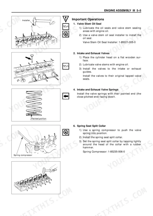
| Engine Assembly Iii (Reassembly) | 94-123 | Piston and Connecting Rod Reassembly, Cylinder Head Reassembly Steps, Rocker Arm and Rocker Arm Shaft Reassembly, Major Component Reassembly Steps I |
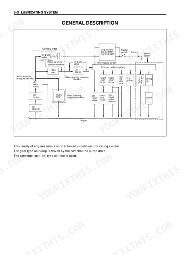
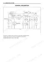
| Lubricating System | 124-129 | |
| Cooling System | 130-133 | General Description, Thermostat |
| Fuel System | 134-143 | General Description, Injection Nozzle, Injection Pump Calibration Data |
| Turbocharger | 144-147 | General Description, Turbocharger Identification, Inspection and Repair |
| Air Compressor | 148-155 | General Description, Disassembly Steps, Inspection and Repair, Reassembly Steps |
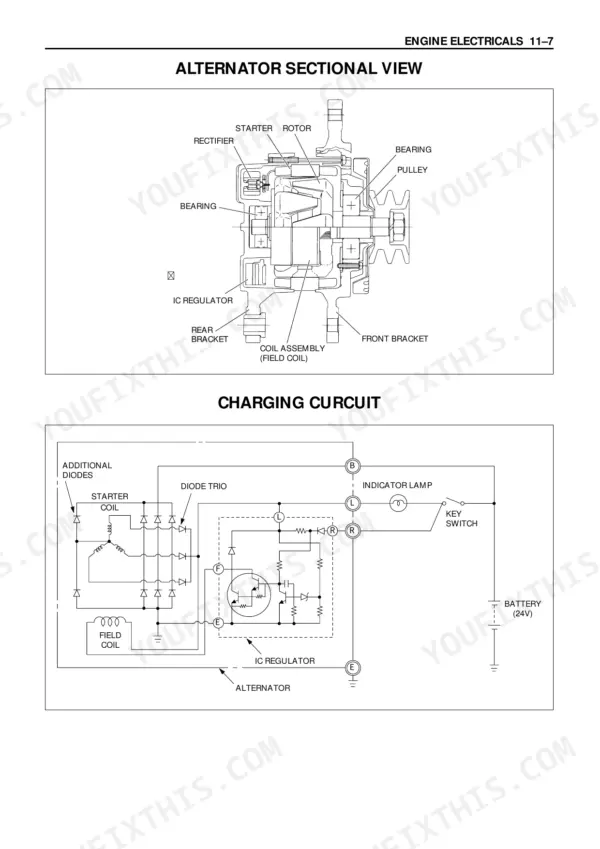
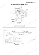
| Engine Electricals | 156-163 | Starter Identification, Starter Main Data and Specifications, Starter Motor Sectional View, Alternator Identification |
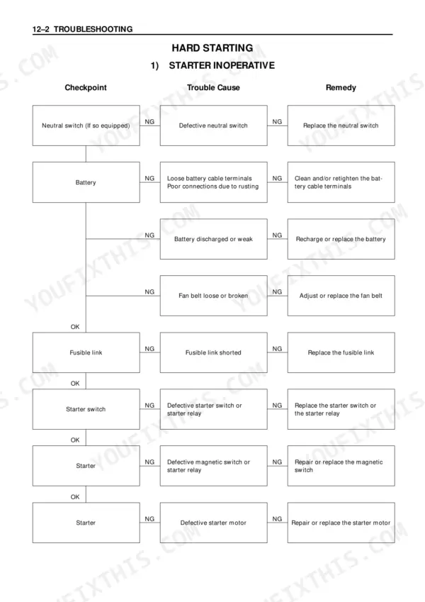
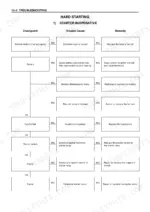
| Troubleshooting | 164-187 | Hard Starting, Unstable Low Idling, Insufficient Power, Excessive Fuel Consumption |
| Special Tool List | 188-191 | |
| Repair Standards | 192-211 | General Rules, Engine Body, Main Operating Parts, Valve System |
| Conversion Table | 212-220 |
Quick Reference Specifications
| Specification | Value | Page |
|---|---|---|
| All Models | ||
| Crankshaft Bearing Cap Bolt Torque | 226-245 (23.0-25.0/166-181) N·m (kgf·m/lb.ft) | p. 104 |
| Connecting Rod Bolt Torque and Angle | 1st step 39 (4/29) N·m (kgf·m/lb.ft), 2nd step 60°–90° | p. 105 |
| Valve Clearance (At cold) | 0.40 mm | p. 7 |
| Compression Pressure (At warm) | 3.0 MPa | p. 7 |
| Injection Starting Pressure | 18.1 MPa | p. 7 |
| Compression Pressure Limit | 2.5 MPa | p. 42 |
| Thermostat Valve Opening Temperature | 80-84 °C | p. 34 |
| Rocker Arm Screw Lock Nut Torque | 21-30 N·m | p. 36 |
| BB-6BG1T | ||
| Lubricating Oil Volume | 21.5 L | p. 8 |
| AA-6BG1, BB-6BG1T | ||
| Coolant Volume (engine only) | 12 L | p. 8 |
| Flywheel Bolt Torque | 197-240 N·m | p. 108 |
| Crankshaft Pulley Nut Torque | 539-637 N·m | p. 109 |