


This is the factory service manual for Mitsubishi S3L, S3L2, S4L, and S4L2 diesel engines, the compact units used in forklifts, generators, compact tractors, and other land and industrial equipment. The 219 page manual carries publication number 99619-12140 and covers disassembly, inspection, correction, and reassembly for every major system.Inside you get full service standards and tightening torques, overhaul timing and compression checks, and step by step procedures for the cylinder head, fuel injection pumps and nozzles, lubrication, cooling, inlet and exhaust, and electrical systems. Adjustment data covers valve clearance, fuel injection timing, and idle speeds.Use it to diagnose overheating, hard starting, or low power, rebuild the top end, or set injection timing correctly. Engine inspection sheets at the back give the wear limits you need for a proper rebuild.
What's Inside This Mitsubishi S3L, S3L2, S4L, S4L2 Manual
| System | Pages | Key Topics |
|---|---|---|
| Safety Cautions | 6-13 | Risk of Fire and Explosion, Risk of Entanglement Into the Machine, Risk of Burn, Exhaust Gas Poisoning, Hearing Damage, Falling Engine Hazard |
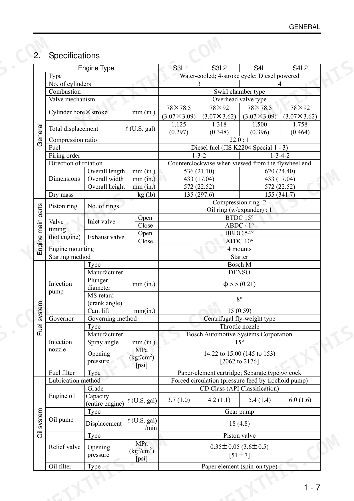
| Engine Overview & Serial Number Identification | 14-23 | Outline Drawing, Fuel System Schematic, Oil System Schematic, Cooling System Schematic, Inlet/Exhaust System Schematic, Engine Serial Number, Engine Model and Application Codes |
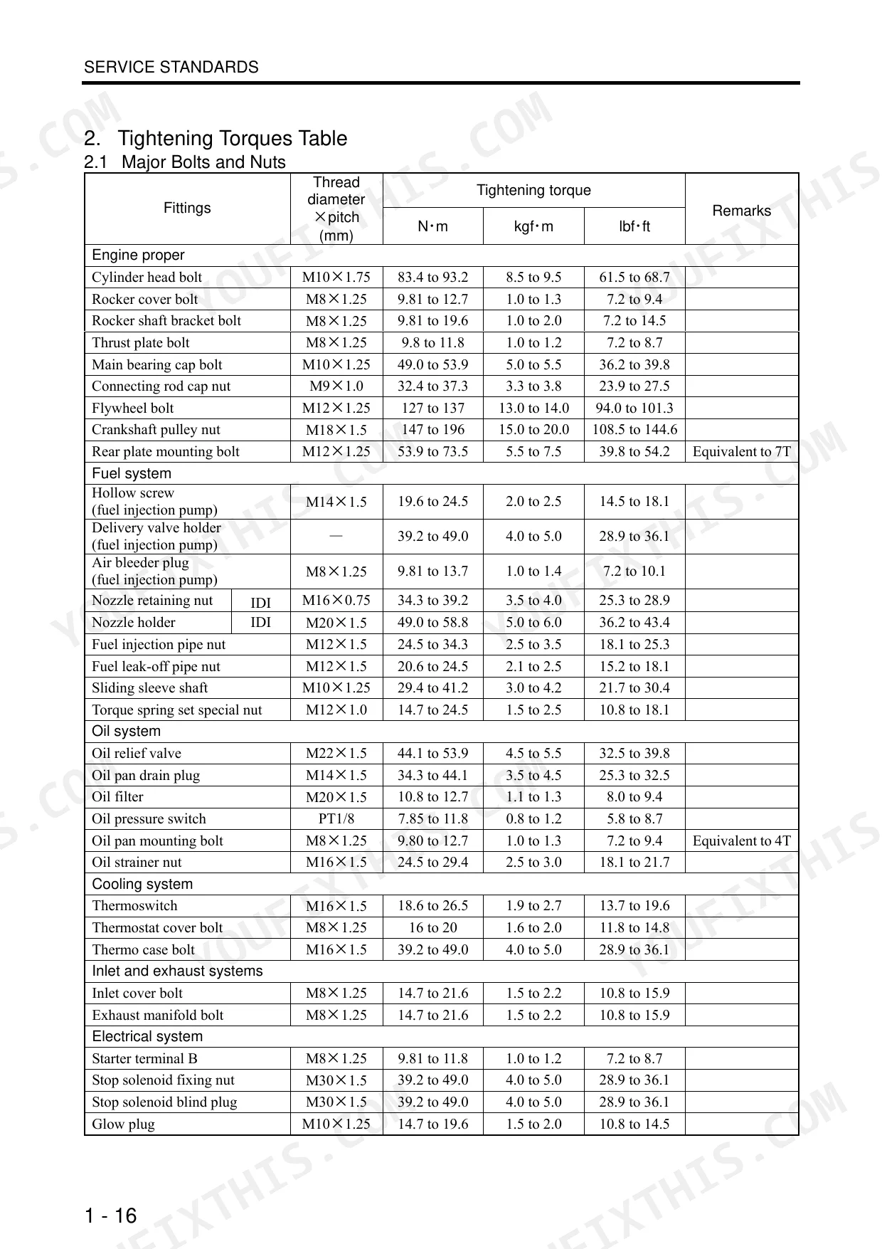
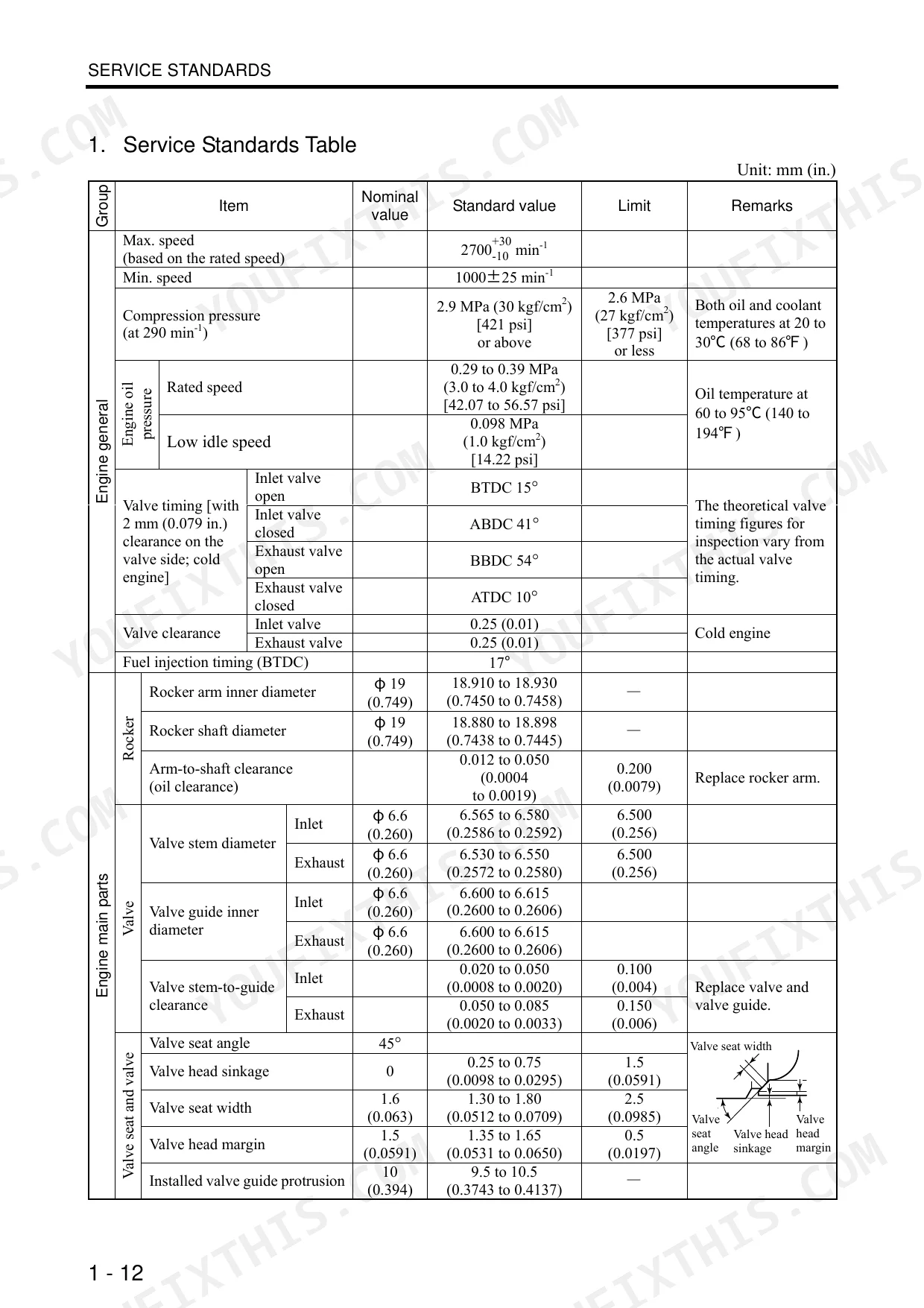
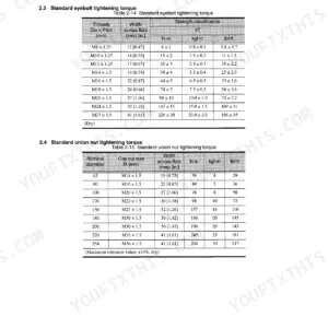
| Service Standards & Tools | 24-37 | Service Standards Table, Tightening Torques (Major Bolts and Nuts, Standard Bolts and Nuts, Standard Eyebolts, Standard Union Nuts, Taper Bolts), Sealants List, General Tools, Special Tools |
| Overhaul Timing & Removal Preparations | 38-43 | Identifying Timing for Overhaul, Measuring Compression Pressure, Compression Pressure Standard Value and Limit, Removing Electric Wiring, Draining Coolant, Draining Engine Oil, Coolant Drain Cock, Oil Pan Drain Plug |
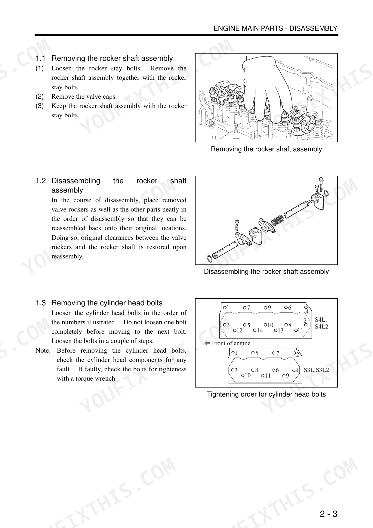
| Engine Main Parts (Cylinder Head, Block, Crankshaft, Pistons) | 44-91 | Cylinder Head Disassembly, Cylinder Head Inspection and Correction, Cylinder Block, Crankshaft, Pistons |
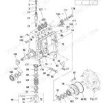
| Fuel System | 92-123 | Fuel Injection Pipes, Fuel Leak-Off Pipe, Fuel Injection Nozzles, Governor and Governor Weights, Fuel Injection Pumps, Sliding Sleeve |
| Lubrication System | 124-135 | Oil Filter, Relief Valve, Oil Pressure Switch, Oil Pan, Oil Strainer, Oil Pump |
| Cooling System | 136-147 | Cooling Fan, Fan Pulley and V-Belt, Thermostat and Thermostat Case, Thermoswitch, Water Pump |
| Inlet and Exhaust Systems | 148-159 | Inlet Cover, Exhaust Manifold, Air Pipe, Exhaust Manifold Mounting Face Distortion, Gasket |
| Electrical System | 160-189 | Starter, Alternator, Stop Solenoid, Glow Plug |
| Engine Adjustment, Running-In Trial and Performance Test | 190-203 | Valve Clearance Inspection and Adjustment, Fuel Injection Timing, Fuel Filter Replacement and Air Bleeding, Low and High Idle Speeds, Fuel Injection Nozzle Inspection, V-Belt Tension |
| Miscellaneous Parts & Engine Inspection Standards | 204-219 | Oil Seals, O-Rings, Bearings, Lock Plates, Split Pins, Spring Pins, Oil Seal Installer, Cylinder Bore, Valve Stem-To-Guide Clearance, Valve Stem Diameter, Valve Seat Angle and Width, Cylinder Head Bottom Face Distortion, Connecting Rod Bearing Oil Clearance |
Quick Reference Specifications
| Specification | Value | Page |
|---|---|---|
| Cylinder head bolt torque | 83.4 to 93.2 N·m (8.5 to 9.5 kgf·m) [61.5 to 68.7 lbf·ft] | p. 29 |
| Nozzle retaining nut torque | 34.3 to 39.2 N·m (3.5 to 4.0 kgf·m) [25.3 to 28.9 lbf·ft] | p. 29 |
| Inlet valve clearance | 0.25 (0.01) mm (in.) | p. 192 |
| Exhaust valve clearance | 0.25 (0.01) mm (in.) | p. 192 |
| Cylinder head gasket replacement | Replace with new parts | p. 23 |
| Cylinder head bottom face distortion (Standard value) | 0.05 (0.002) or less mm (in.) | p. 25 |
| Cylinder head bottom face distortion (Limit) | 0.10 (0.004) mm (in.) | p. 25 |
| Thermostat opening temperature | 82±1.5℃ (179.6±2.7°F) | p. 25 |
| Thermostat 8 mm (0.32 in.) valve lift temperature | 95℃ (203°F) | p. 25 |
| Injection nozzle spray angle | 15° | p. 25 |
| Injection nozzle opening pressure | 14.22 to 15.00 MPa (145 to 153 kgf/cm²) [2062 to 2176 psi] | p. 25 |
| Injection pump plunger diameter | φ5.5 (0.21) mm (in.) | p. 25 |
Mitsubishi S3L, S3L2, S4L, S4L2 Common Problems This Manual Covers
Overheating and coolant loss
Owners frequently report overheating that leads to white smoke and lost coolant, often from a stuck thermostat, worn water pump, or restricted passages. The cooling section covers testing the thermostat, which opens at around 82 degrees C, and inspecting the water pump.
Manual Section: Cooling System - Disassembly, Inspection and Reassembly p. 140Blown head gasket after overheating
Repeated overheating can crack the cylinder head or fail the head gasket, showing up as white smoke and coolant loss. This section walks through inspecting and correcting the cylinder head, including checking bottom face distortion.
Manual Section: Engine Main Parts - Inspection and Correction p. 62Hard starting after fuel service
Air trapped in the fuel system after filter or injector work is a common cause of hard or no start. The engine adjustment section covers bleeding the fuel filter of air and inspecting the injection nozzles.
Manual Section: Engine - Inspection / Adjustment, Running-in Trial and Performance Test p. 190Low compression and power loss
Worn cylinders, pistons, or valves reduce compression and cause poor power and hard starting. The overhaul timing section explains how to measure compression pressure and compare it against the standard value and limit.
Manual Section: Overhaul Timing p. 38Black smoke and rough running
Black smoke under load with rough running usually points to injection nozzle or pump condition. This section covers disassembling, inspecting, and reassembling the fuel injection nozzles.
Manual Section: Fuel System - Disassembly, Inspection and Reassembly p. 100Starter will not crank
A no crank condition can come from the starter itself once the battery and wiring check out. The electrical section details removing, inspecting, correcting, and reassembling the starter.
Manual Section: Electrical System - Disassembly, Inspection and Reassembly p. 166Frequently Asked Questions
Which engines does this manual cover?
It covers the Mitsubishi S3L, S3L2, S4L, and S4L2 diesel engines used in land and industrial applications, under publication number 99619-12140. Note that the fuel injection pump internals, governor, and turbocharger are handled in a separate manual.
How do I get the manual after buying?
You download the PDF straight after purchase, so you can start using it right away. There is no wait for shipping.
What is the cylinder head bolt torque?
The service standards list the cylinder head bolt torque as 83.4 to 93.2 N·m (8.5 to 9.5 kgf·m). Full tightening torques for major bolts and nuts are tabulated in the Service Standards section. p. 24
What is the valve clearance and where is it set?
Inlet and exhaust valve clearance is 0.25 mm. The engine inspection and adjustment section covers preparing for and checking valve clearance along with fuel injection timing. p. 190
How quickly can I access this manual after buying?
A 219-page Service Manual in searchable PDF format, available the moment you complete checkout. View it on a computer, tablet, or phone. There is no shipping wait.
Are there any print restrictions on this manual?
The PDF is DRM-free, so print whatever sections you need to take out to the shop. Standard letter or A4 paper works fine.


Reviews
There are no reviews yet.