


This is the factory service manual for the Mustang 2060 and 2070 skid steer loaders, publication 001-69975, covering 1995 through 1997 machines from serial number SE97H001591 and up. The 2060 runs an Isuzu 4JB1 and the 2070 the turbocharged Isuzu 4JB1T, both driving a 3,000 PSI hydraulic system.Across 116 pages it covers safety equipment and interlocks, steering controls, the hydraulic and hydrostatic drive systems, the chain case, the engine, and the 12 volt electrical system, with specifications, torque tables, and troubleshooting charts throughout.Independent mechanics and owners use it to diagnose no start and interlock faults, test and rebuild the hydraulics and hydrostatic drive, service the chain case, and trace electrical problems. Model-specific values, such as the different engine oil capacities for the 2060 and 2070, are separated clearly. It is a downloadable, printable PDF.
What's Inside This Mustang 2060, 2070 Manual
| System | Pages | Key Topics |
|---|---|---|
| Introduction | 3-3 | Manual Purpose, Safety Equipment, Serial Number Tag Location, Manufacturing Policy, Figure 0-1 |
| Serial Number System | 4-5 | Importance of Serial Number, And 2070 Serial Number System Breakdown (Example Model 2060 S/N SE95M000136), Iso Recommendations |
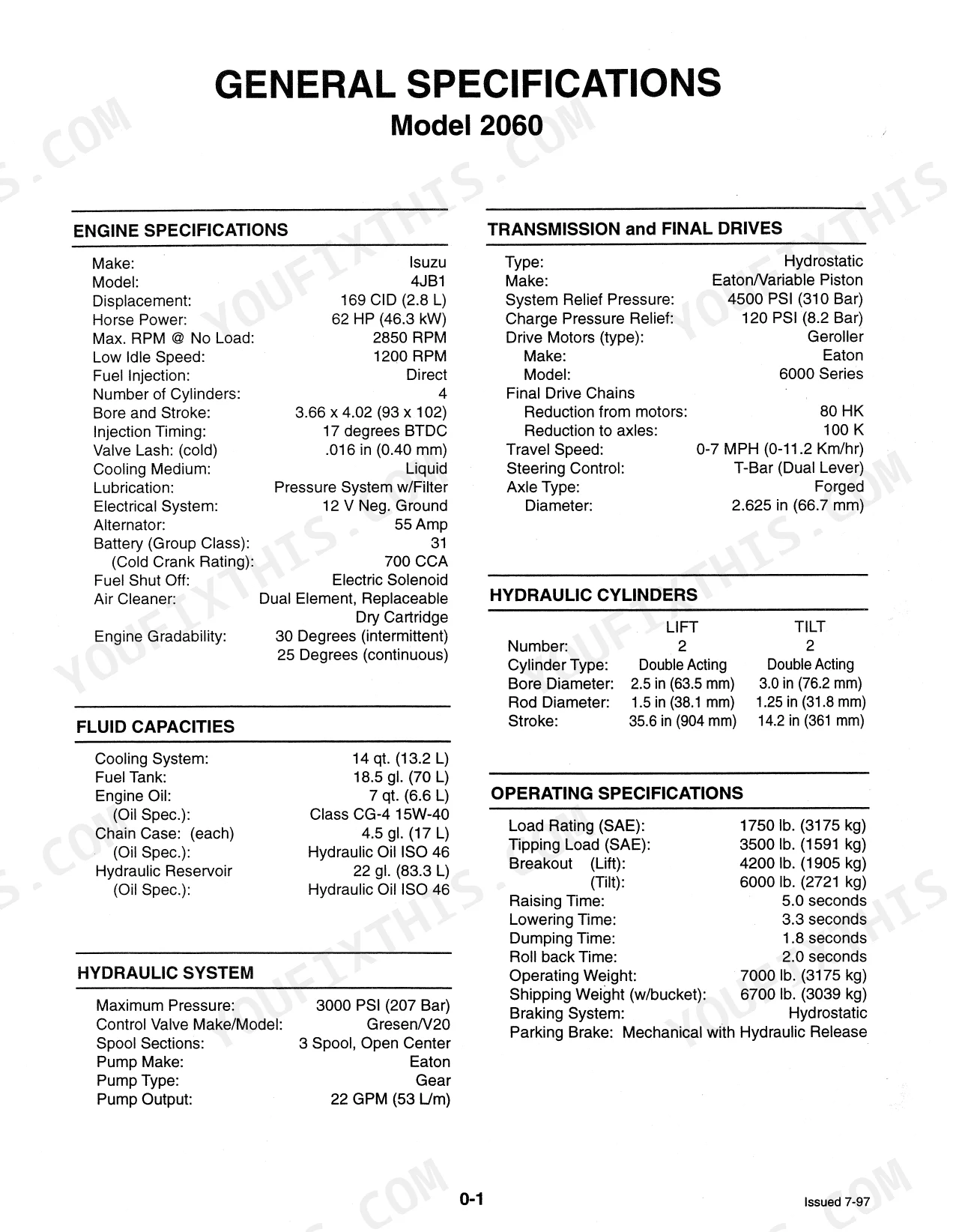
| Specifications | 6-7 | Engine Specifications, Transmission and Final Drives, Hydraulic Cylinders, Fluid Capacities, Operating Specifications |
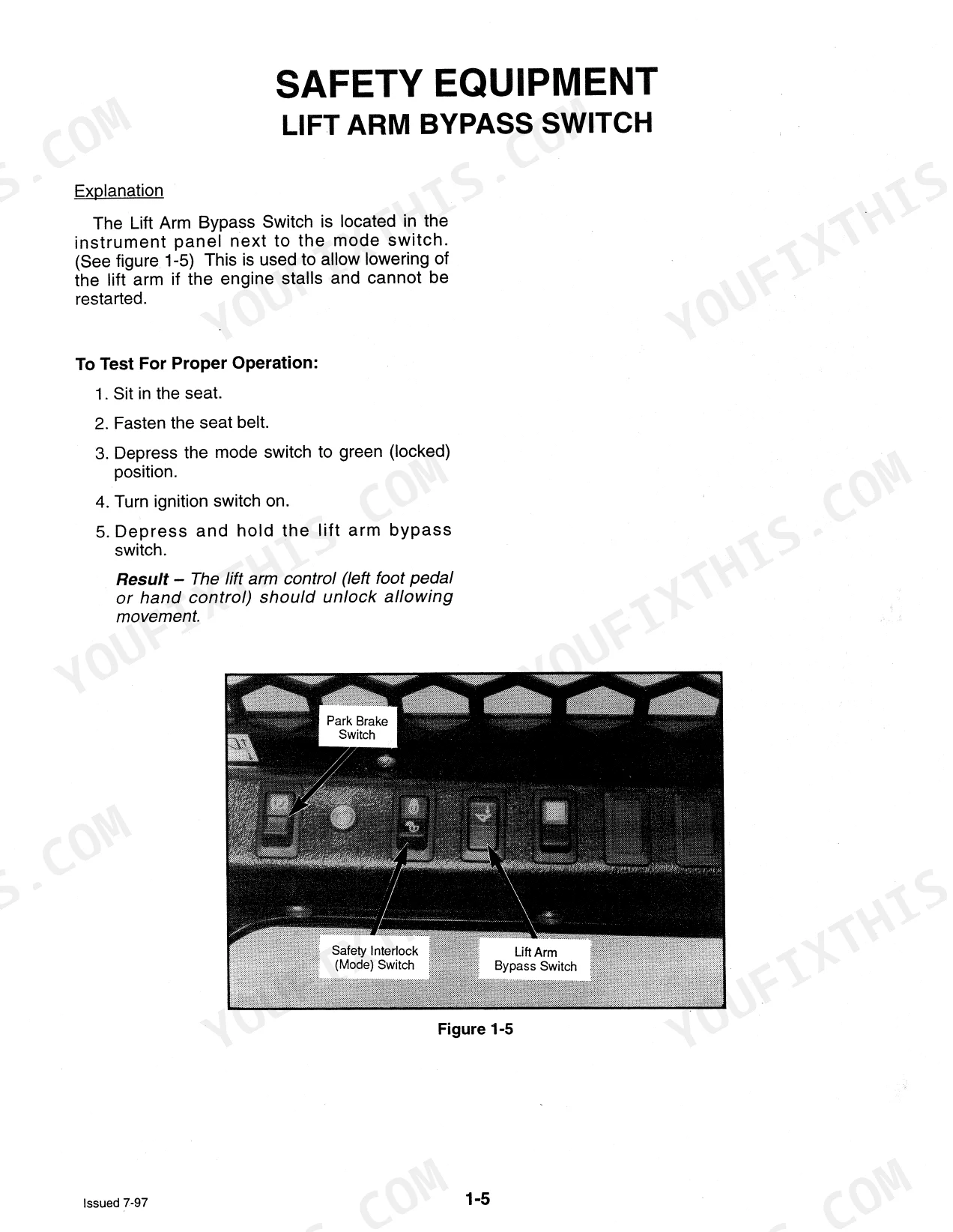
| Safety Equipment | 8-21 | Roll Over Protective Structure (ROPS), Lift Arm Stops, Safety Interlocks, Lift Arm Bypass Switch, Parking Brake, Troubleshooting Parking Brake |
| General Information | 22-38 | System Contamination Control, Hydraulic Fluids, Maintenance Chart, Pre-Delivery Check List, 50 Hour Check List, Access Panels, Standard Torque Value Specifications |
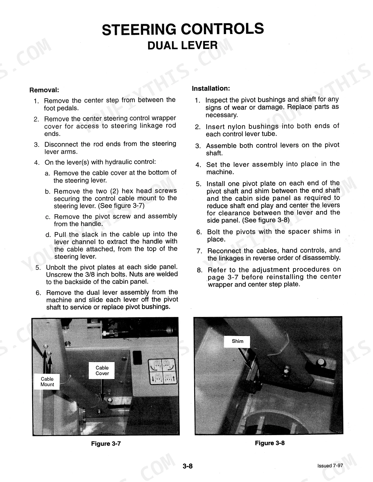
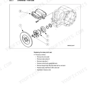
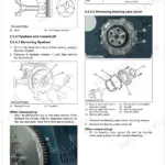
| Steering Controls | 39-47 | Troubleshooting, Neutral Centering Device Adjustments, Neutral Centering Device Service and Repair, Diagram, Steering Controls - T-Bar, Steering Controls - Dual Lever |
| Hydraulic System | 48-68 | Troubleshooting, Flow Diagram, Controls, Lift Circuit Leak Down Test, Tilt Circuit Leak Down Test, Hydraulic Cylinders Testing, Hydraulic Cylinder Service and Repair |
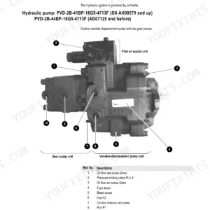
| Hydrostatic Drive System | 69-84 | Troubleshooting, Flow Diagram, Flow Schematic, System Checks (Charge Pressure, Power Check, Directional Check/Relief Valve...), Hydrostatic Pump, Removal and Installation... |
| Chain Case | 85-94 | Explanation, Trouble Shooting, Axle Housing R & R, Torque Specifications for Chain Case, Drive Chain & Sprocket R & R |
| Engine | 95-104 | Troubleshooting, Engine / Hydrostatic Pump Removal and Installation, Cooling System, Cooling System Trouble Shooting, Fuel System, Injection Timing Check, Air Cleaner |
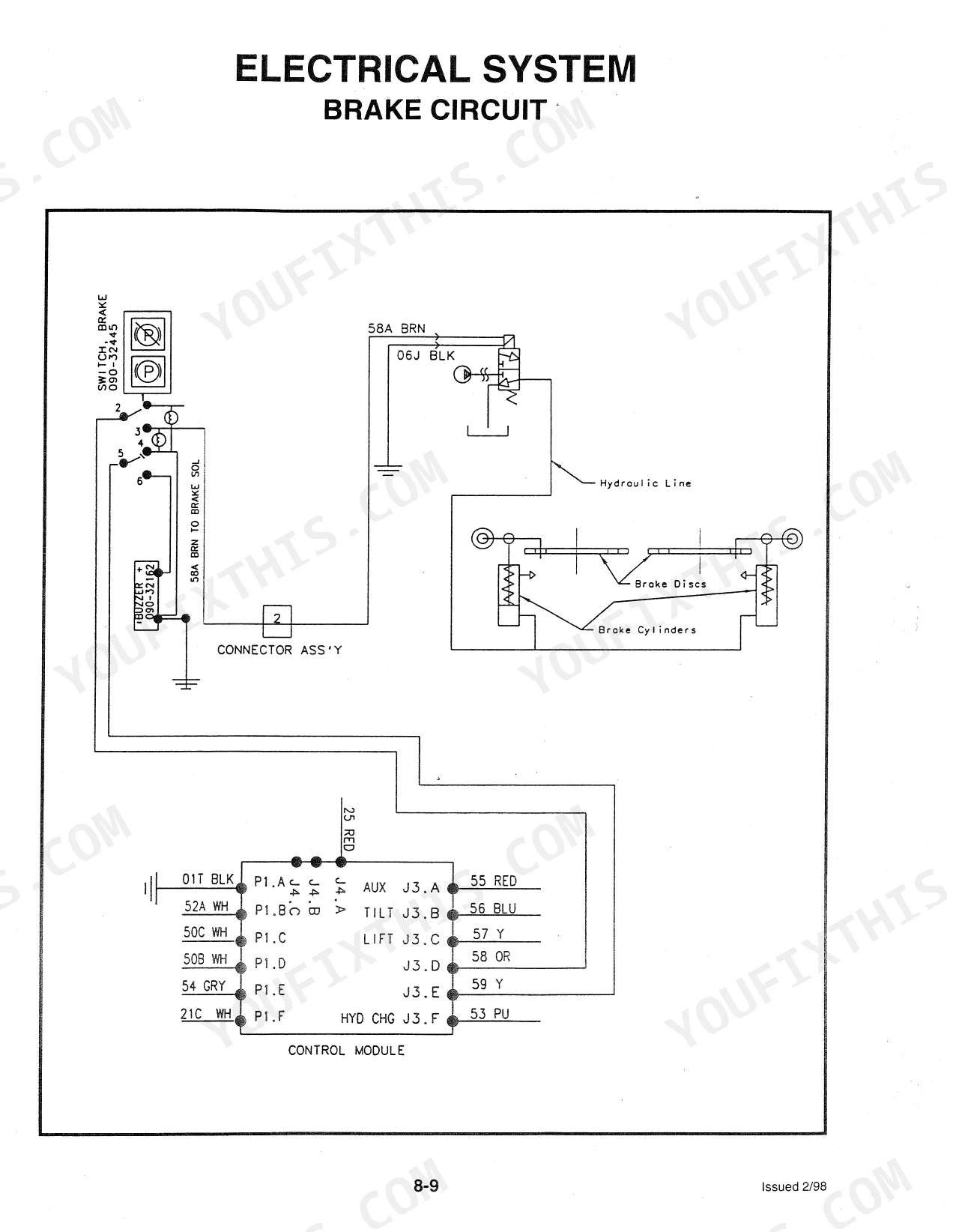
| Electrical System | 105-116 | Trouble Shooting, Interlock Circuit, Interlock Circuit Testing, Troubleshooting Interlock Circuit, Brake Circuit Wiring Diagram, Control Module Tests, Alternator Charging Circuit |
Quick Reference Specifications
| Specification | Value | Page |
|---|---|---|
| All Models | ||
| Auxiliary hydraulic pressure (check range) | 2920-3100 PSI / 201-213.5 bar | p. 61 |
| Flow restriction pressure (adjustment target) | 2700 PSI / 186 bar | p. 61 |
| Lift cylinder rod nut torque | 215-225 ft. lbs. (292-305 Nm) | p. 60 |
| Drive motor mounting nuts torque | 75 ft. lb./101 Nm | p. 83 |
| Drive motor retaining nut torque | 275 ft. lb./373 Nm | p. 83 |
| Plunger Lifted Position At Fuel Injection Starting Timing | 0.50 mm (0.0197 in) | p. 102 |
| Injection timing gauge probe depression | approximately 1 mm (0.039 in) | p. 102 |
| Hydraulic System Maximum Pressure | 3000 PSI (207 Bar) | p. 6 |
| Transmission System Relief Pressure | 4500 PSI (310 Bar) | p. 6 |
| Drive Motor Sprocket Retaining Nut Torque | 275 ft. lbs. | p. 91 |
| 2060 | ||
| Engine Oil Capacity | 7 quarts (6.6 L) | p. 6 |
| 2070 | ||
| Engine Oil Capacity | 8.9 quarts (8.4 L) | p. 7 |
Mustang 2060, 2070 Common Problems This Manual Covers
Engine will not turn over
A no crank fault on the 2060 or 2070 usually sits in the interlock or starting circuit, and owners often report the parking brake switch failing to light. The Electrical System section covers the interlock circuit testing and control module tests to isolate it.
Manual Section: Electrical System p. 105Parking brake indicator does not light
When the parking brake light stays off at key-on, the machine may not enable startup, pointing to the brake switch or interlock wiring. The Safety Equipment section covers parking brake testing, troubleshooting, and repair.
Manual Section: Safety Equipment p. 8Weak or slow hydraulic functions
Slow lift or tilt and erratic hydraulics trace to the pump, control valve, or cylinder leakage. The Hydraulic System section provides the flow diagram, leak down tests, and cylinder service procedures.
Manual Section: Hydraulic System p. 48Loss of drive power
Reduced or uneven travel comes from the closed loop hydrostatic circuit. The Hydrostatic Drive System section gives the flow schematic and the charge pressure, power, and relief valve checks to diagnose it.
Manual Section: Hydrostatic Drive System p. 69Drive chain slack or sprocket wear
Worn chains and sprockets produce noise and poor drive on these skid steers. The Chain Case section covers the axle housing removal, drive chain and sprocket service, and the chain case torque specifications.
Manual Section: Chain Case p. 85Contamination shortens hydraulic life
Dirt introduced during service is a leading cause of hydraulic and hydrostatic failure. The General Information section covers contamination control, hydraulic fluids, and the maintenance and check lists that prevent it.
Manual Section: General Information p. 22Frequently Asked Questions
Which machines and serial numbers does this cover?
It covers the Mustang 2060 and 2070 skid steer loaders, publication 001-69975, from serial number SE97H001591 and up, built 1995 to 1997. The 2060 uses the Isuzu 4JB1 and the 2070 the Isuzu 4JB1T.
Are the 2060 and 2070 specs listed separately?
Yes. The Specifications section separates model-specific values, for example engine oil capacity of 7 quarts on the 2060 versus 8.9 quarts on the 2070, so you use the right figure for your machine. p. 6
Does it include electrical and interlock diagnostics?
The Electrical System section documents the interlock circuit, interlock testing, brake circuit wiring diagram, control module tests, and the alternator charging circuit for tracing no start and electrical faults. p. 105
Where are the torque specifications?
Standard and metric torque value tables and torque procedures for hoses and fittings are in the General Information section, with additional chain case torque values in the Chain Case section. p. 22
What do I get after purchasing this Mustang 2060, 2070 manual?
A 116-page Service Manual in searchable PDF format, available the moment you complete checkout. View on computer, tablet, or phone — no shipping wait.
Can I print specific sections of this Mustang 2060, 2070 Service Manual?
Yes. The PDF has no DRM restrictions — print any page or section you need for your shop. Works with any standard printer.
Are hydraulic system diagrams in this Mustang 2060, 2070 Service Manual?
Included. Hydraulic system schematics cover all circuits, control valves, and component specifications for the Mustang 2060, 2070.


Reviews
There are no reviews yet.