


This is the factory service manual for the Mustang ML 28 all-wheel-steer loader, part number 918133, covering 2005 machines powered by a Yanmar 4TNV88 diesel rated at 38 hp (28 kW). At 172 pages it is graded High for document quality and carries a full text layer, so it searches cleanly.It documents the loader end to end: scheduled maintenance and fluids, the engine and cooling system, the hydrostatic power train, axles, brakes, all-wheel steering, the electrical system, work hydraulics, heating, and a complete torque specification table.Owners and independent mechanics use it to run maintenance on the correct intervals, chase overheating and hydraulic faults, adjust the parking brake, and service the drive and steering circuits. Wheel nut torque, filter change intervals, and belt tension are all called out. It is a searchable PDF you can download and print at home.
What's Inside This Mustang ML 28 Manual
| System | Pages | Key Topics |
|---|---|---|
| Maintenance | 27-64 | Fluids and Lubricants, Explanation of Symbols for the Maintenance Decal, Maintenance Schedule, Maintenance Items, Refueling (Stationary Fuel Pumps), Fuel Prefilter |
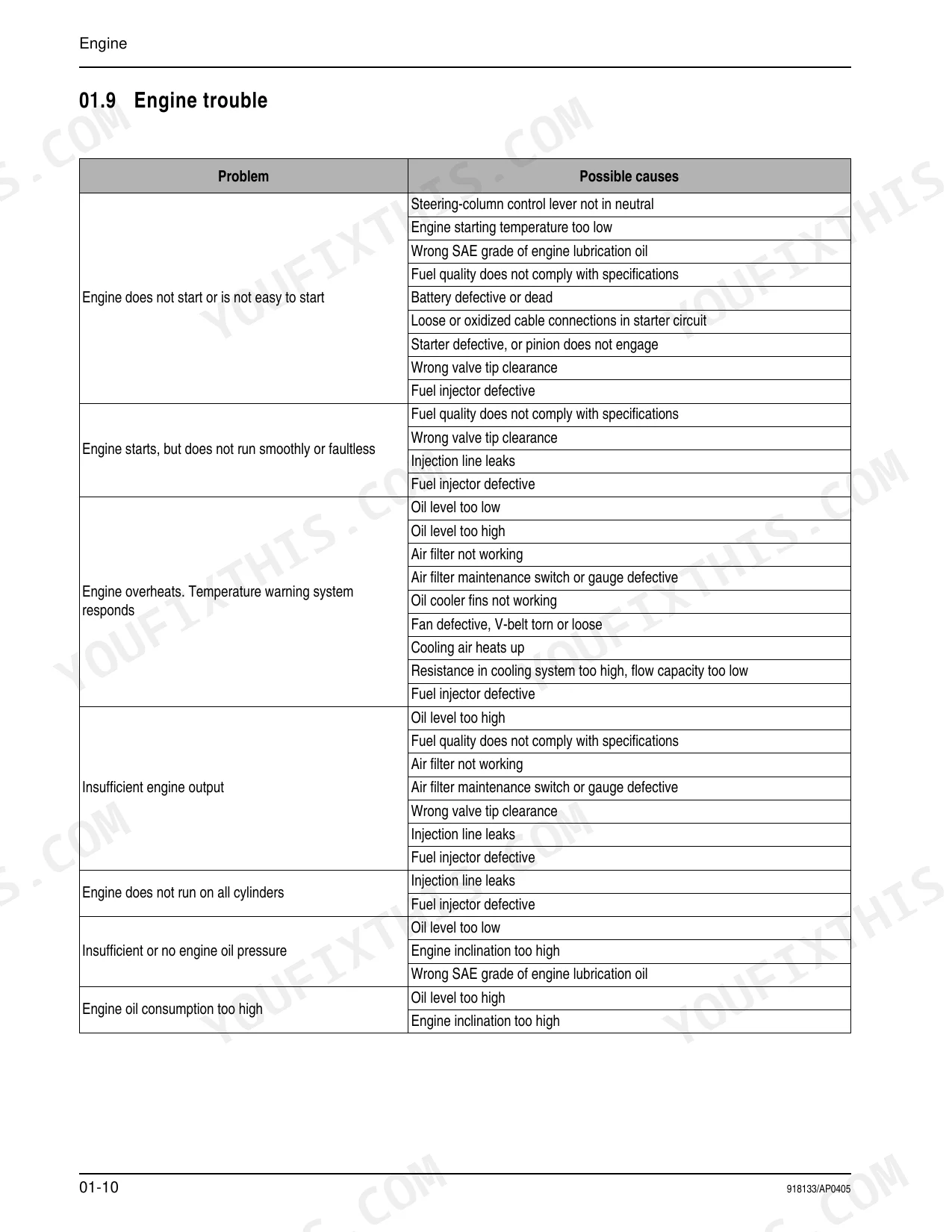
| Engine | 65-76 | Specifications (Engine Type Decal), Engine Overview, Fuel Injection System, Fuel Injection Nozzle, Engine Valve Tip Clearance, Engine Cooling: Overview, Fuel System: Overview |
| Power Train | 77-94 | Description: Variable Displacement Pump a 10 Vg 28 Da, Description: Hydraulic Motor Vm 45 Ez 6, Fuel System: Overview, Measuring Points: Variable Displacement Pump |
| Axles | 95-112 | Type Decal – Axle, Drain, Fill and Check Plug, Tightening Values Lb-Ft, Screw Connections |
| Brakes | 113-118 | Overview: Brake System, Readjustment: Parking Brake (Replacing Brake Linings), Basic Setting: Cables (for Inching, – Parking Brake, For Parking Brake) |
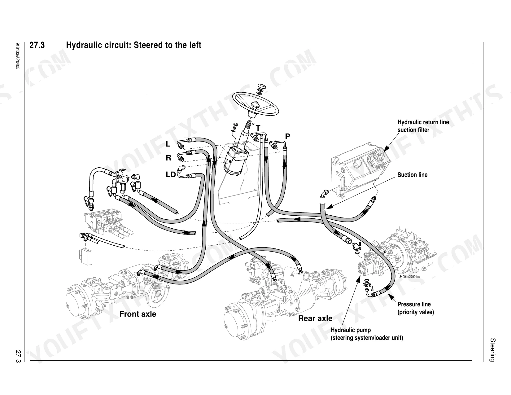
| Steering | 119-124 | Overview – Steering Circuit, Steering Diagram, Hydraulic Circuit: Steered to the Left, Hydraulic Circuit: Steered to the Right, Hydraulic Ports on Servostat |
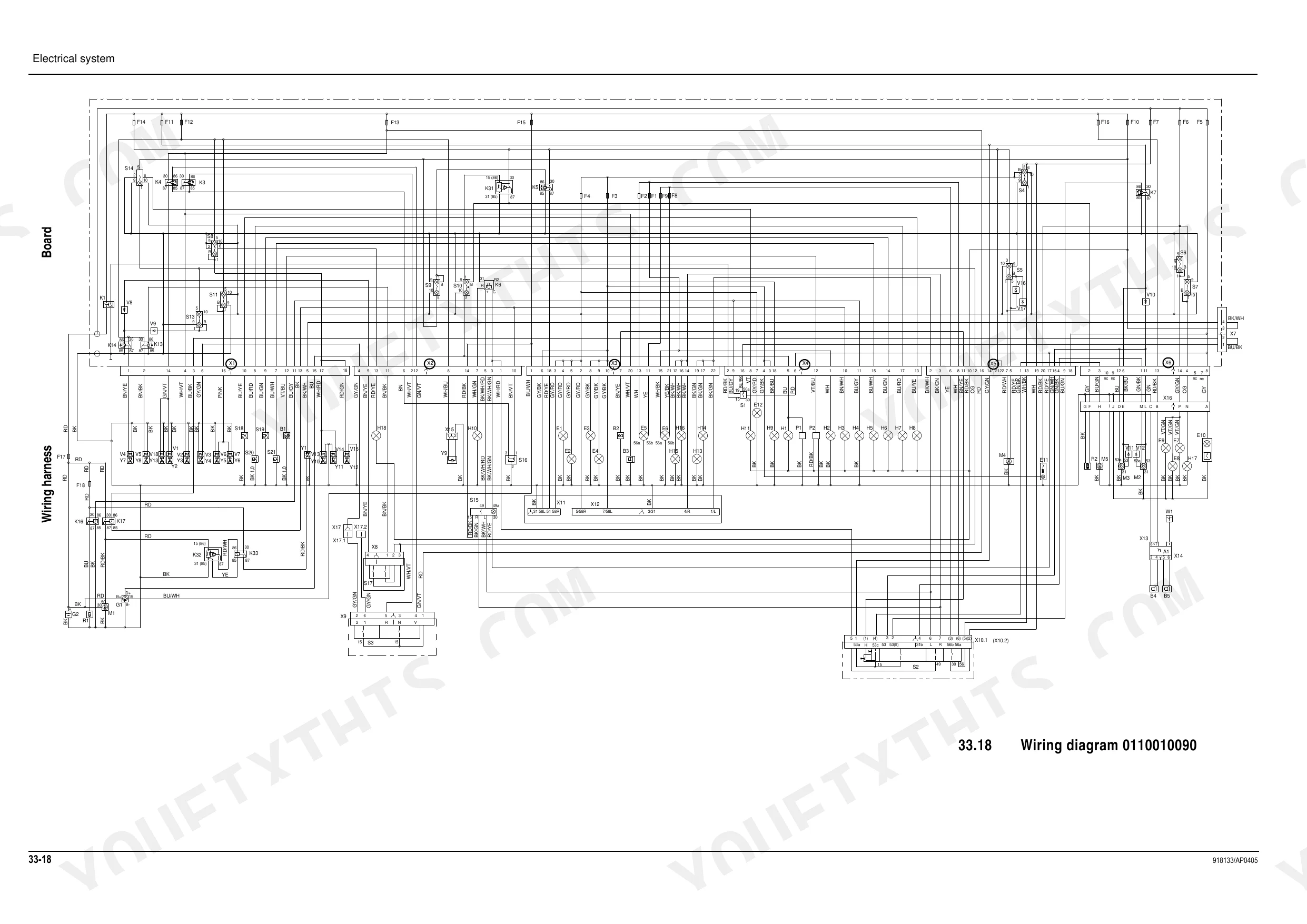
| Electrical System | 125-148 | Ohm's Law; Power, Measuring Equipment, Measuring Methods, Terminal Description, Cable Color Coding |
| Hydraulics | 149-166 | Hydraulics Diagram – Pilot Control, Hydraulics Diagram – Float Position, Hydraulic Circuit: Pump – Control Valve – Tank, Overview: Control Valve, Hydraulic Ports on Control Valve |
| Heating | 167-170 | Heating Circuit Overview (Heater Nozzle, Temperature Controller, Heater, Reflux, Lock Lever, Intake Filter, Feed), Notes |
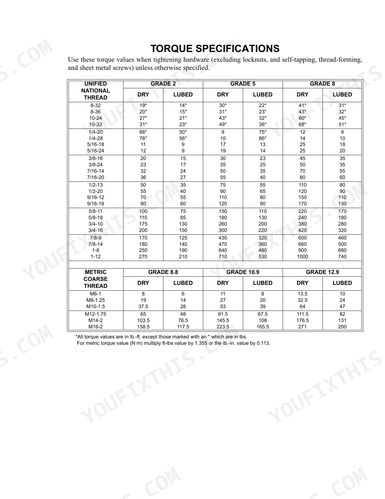
| Torque Specifications | 171-172 | Unified National Thread Torque Values, Metric Coarse Thread Torque Values, Conversion Information |
Quick Reference Specifications
| Specification | Value | Page |
|---|---|---|
| General torques for cap screws (Grade 7 (8.8)) | M4: 2 lb-ft (3 Nm) to M30: 996 lb-ft (1350 Nm) | p. 24 |
| Hydraulic system specific safety instructions | All lines carrying hydraulic oil must be depressurized prior to any maintenance and repair work. To do this: Lower all hydraulically controlled attachments to the ground. Actuate all the control levers of the hydraulic control valves several times. Apply the parking brake to prevent the machine from rolling away before you perform service and maintenance work. | p. 45 |
| Hydraulic oil return filter replacement interval | 1500 service hours (yearly) | p. 49 |
| Air filter replacement interval | 1200 service hours (yearly) | p. 42 |
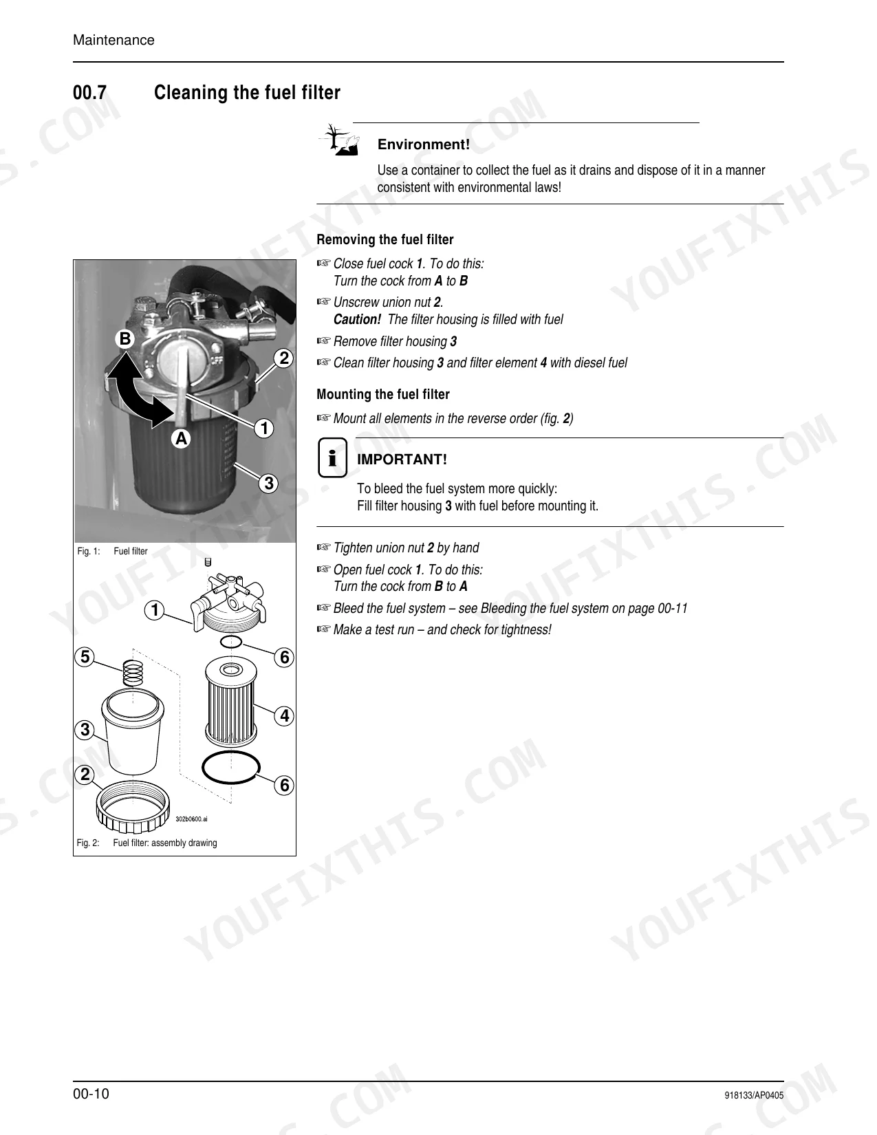
| Fuel filter replacement interval | 500 service hours | p. 30 |
| V-belt tension deflection | 0.39'' (10 mm) | p. 44 |
| Coolant thermostat opening temperature | 162° - 181° F (72° - 83° C) | p. 65 |
| Radiator cap pretension | 13 psi (0.9 bar) | p. 65 |
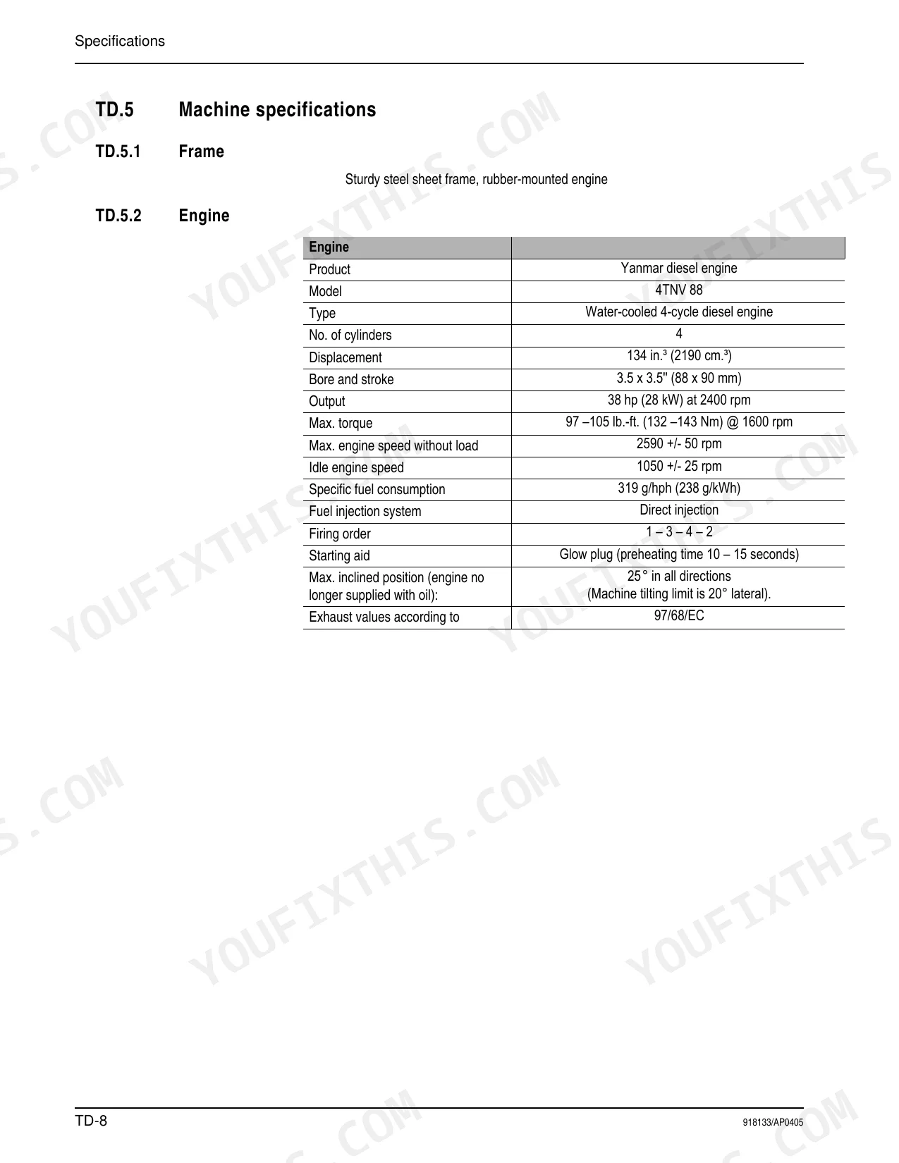
| Engine Output | 38 hp (28 kW) at 2400 rpm | p. 16 |
| Engine Idle Speed | 1050 +/- 25 rpm | p. 16 |
| Engine Valve Tip Clearance | .008'' (0.2 mm) | p. 65 |
| Hydraulic Pump Max. Service Pressure | 5076 psi (350 bar) | p. 17 |
Mustang ML 28 Common Problems This Manual Covers
Engine overheating during operation
Overheating on the ML 28 commonly comes from low coolant, a dirty radiator, or a failed thermostat. The Engine section documents the cooling system overview along with the thermostat and radiator cap specifications needed to confirm the fault.
Manual Section: Engine p. 65Loader arms lift slowly or stall
Weak or uneven loader movement usually points to low hydraulic oil, internal cylinder leakage, or a worn control valve. The Hydraulics section provides the circuit diagrams and control valve overview for diagnosis.
Manual Section: Hydraulics p. 149Machine moves weakly or not at all
Drive faults that resemble a hydrostatic problem trace to the variable displacement pump or hydraulic motor. The Power Train section describes the A 10 VG 28 DA pump and VM 45 EZ 6 motor with their measuring points.
Manual Section: Power Train p. 77Parking brake drags or will not hold
A parking brake that slips or drags often needs the linings replaced or the cables readjusted. The Brakes section gives the brake system overview and the basic cable settings for the parking brake.
Manual Section: Brakes p. 113Neglected filter and belt maintenance
Skipped service on the air, fuel, and hydraulic filters or a slack V-belt leads to hard starting, weak hydraulics, and cooling loss. The Maintenance section carries the full schedule and the replacement intervals for each item.
Manual Section: Maintenance p. 27All-wheel steering faults
Erratic or heavy steering on the all-wheel-steer loader traces to the steering circuit and servostat. The Steering section provides the steering diagram and the hydraulic circuit for left and right turns.
Manual Section: Steering p. 119Frequently Asked Questions
What does this manual cover?
It is the service manual for the Mustang ML 28 all-wheel-steer loader, part number 918133, Revision A dated 04/05. It covers the 2005 machine with the Yanmar 4TNV88 engine.
What is the engine output of the ML 28?
The Yanmar 4TNV88 is rated at 38 hp (28 kW) at 2400 rpm, with an idle speed of 1050 rpm. Full engine and machine specifications are listed in the Specifications section. p. 16
Are torque specifications included?
Yes. The Torque Specifications section carries the unified national and metric coarse thread torque values, and general cap screw torques run from M4 at 2 lb-ft up to M30 at 996 lb-ft. p. 171
Does it cover hydraulic service?
The Hydraulics section provides the pilot control and control valve diagrams, and the Maintenance section adds the safety steps for depressurizing all hydraulic lines before any repair work. p. 149
How quickly can I access this Mustang ML 28 manual after buying?
Instant PDF download. The full 172-page searchable Service Manual lands in your hands right after payment. Open it on a laptop, tablet, or phone in the shop.
Is this Mustang ML 28 Service Manual printable?
Yes. The PDF has no DRM restrictions, so print any page or section you need for the shop. Works with any standard printer.
Are there wiring harness diagrams in this Mustang ML 28 manual?
Included. The Mustang ML 28 Service Manual covers complete wiring harness diagrams, electrical circuits, and connector pinouts.


Reviews
There are no reviews yet.