


This is the factory service manual for the Mustang 930, 940, and 960 skid steer loaders, part number 000-12909, built from 1988 to 1991, with a supplement covering the E-Series 920E, 930A, and 940E machines. Engines documented include the Yanmar 3TN82E and 4TN82E and the Isuzu 4JB1 diesel.Across 134 pages the manual covers specifications, safety equipment, steering controls, the hydraulic system, the hydrostatic drive, the chain case and final drives, the engine, and the electrical system, with troubleshooting charts, torque tables, and wiring diagrams.With this PDF you can check charge pressure, run lift and tilt leak-down tests, service the chaincase and brakes, rebuild hydraulic cylinders, and diagnose the E-Series interlock and fuel solenoid circuits, using the same reference a Mustang technician relies on.
What's Inside This Mustang 920–960 Manual
| System | Pages | Key Topics |
|---|---|---|
| Introduction | 3-3 | Manual Purpose and Scope, Operator Safety Priority, Model and Serial Number Location, Product Changes and Specifications, Figure 0-1 Serial Number Tag Location |
| Serial Number System | 4-5 | Serial Number System Breakdown, Serial Number Example (Fiscal Year 1990 Machine, Model 940, Sequence Number, Month of Build February), Service Manual Terminology |
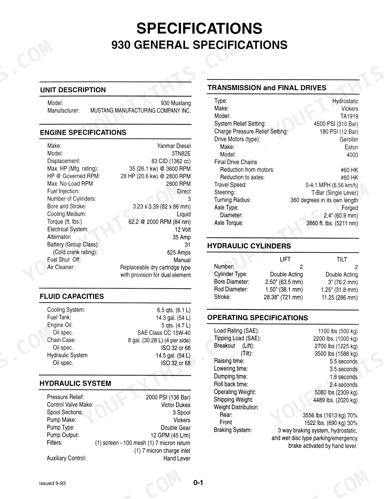
| Specifications | 6-9 | 930 General Specifications, 940 General Specifications, 960 General Specifications |
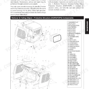
| Safety Equipment | 10-18 | Roll Over Protective Structure (Removal and Installation), Lift Arm Stops, Seat Belt Lock-Out (Adjustments, Spool Lock Rod), Parking Brake (Adjustment), Neutral Start Switches |
| General Information | 19-33 | System Contamination Control, Hydraulic Fluid, Maintenance Chart, Pre-Delivery Check List, 50 Hour Check List, Access Panels, Standard Torque Value Specifications |
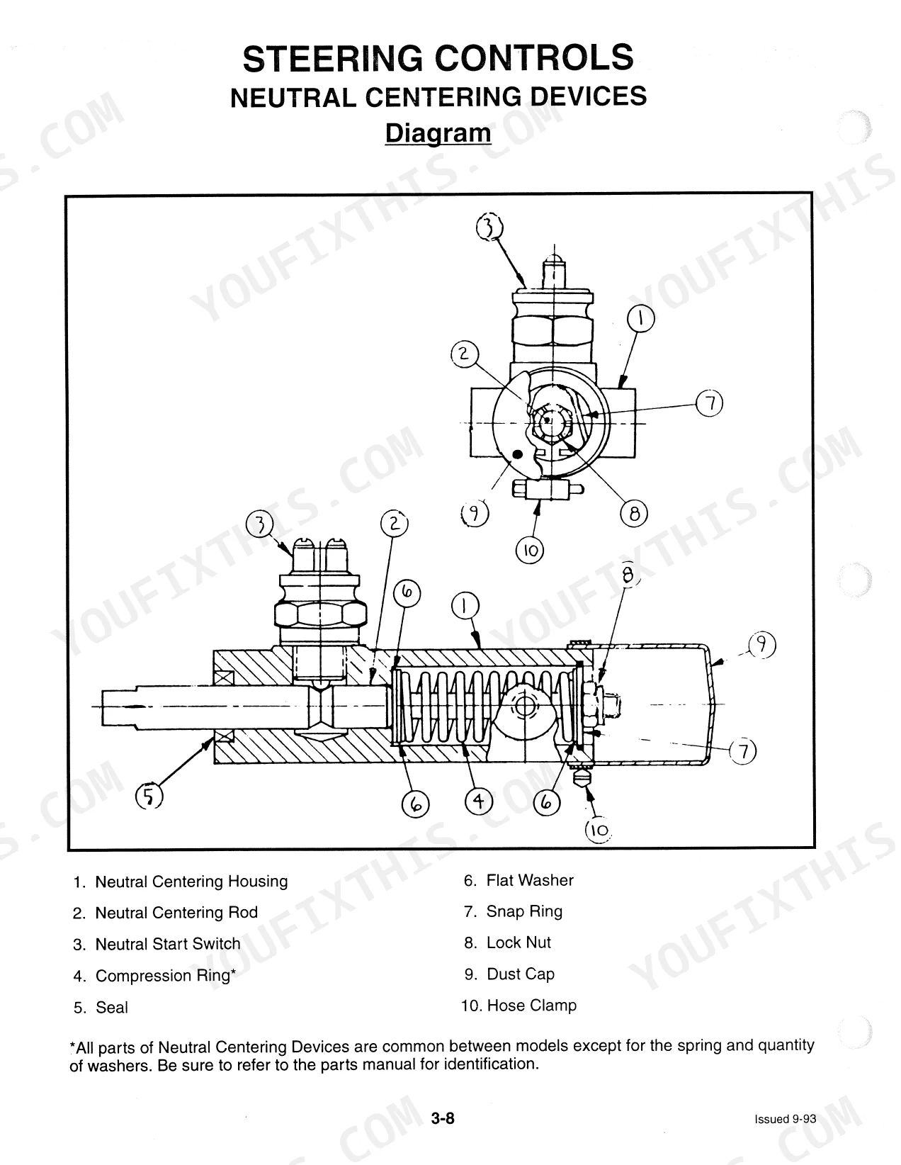
| Steering Controls | 34-41 | Troubleshooting, T-Bar Adjustments, T-Bar Removal and Installation, Neutral Centering Device Adjustments, Neutral Centering Device Service and Repair, Diagram |
| Hydraulic System | 42-64 | Troubleshooting, Pressure Check, Lift Circuit Leak Down Test, Tilt Circuit Leak Down Test, Hydraulic Cylinder Testing, Hydraulic Cylinder Service and Repair |
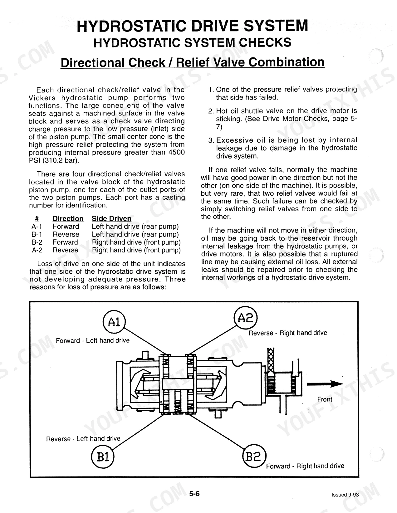
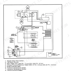
| Hydrostatic Drive System | 65-79 | Troubleshooting, Drive System Diagram, System Checks (Charge Pressure Checks, Directional Check / Relief Valve Combination, Closed Loop, Piston Pump, Hydrostatic Drive Motor) |
| Chain Case | 80-98 | Troubleshooting, Brake Assembly (Service and Repair I, Input Drive Shaft Service and Repair Ii) |
| Engine | 99-110 | Troubleshooting, Engine / Hydrostatic Pump Removal and Installation, Engine Components Removal and Installation, Cooling System, Cooling System Trouble Shooting, Fuel System |
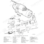
| Electrical System | 111-120 | Troubleshooting, Wiring Diagram, & 940 Wiring Diagram, Instrument Panel, Starting Circuit, Starter Motor - Disassembly, Charging Circuit, Alternator - Disassembly |
| E-Series Service Manual | 121-122 | Applicable Models, Manual Supplement Information, Manual Identification, Manufacturer Contact Information |
| E-Series Interlock Explanation | 123-124 | Hydraulic Control Valve Spool Locks, Solenoid Control of Spool Locks and Fuel Lever, Safety Interlock Switches, Figure 9-1 Electric Solenoid, Figure 9-2 Fuel Solenoid |
| E-Series Wiring Diagram | 125 | Battery and Charging System, Starter Circuit, Fuel Solenoid and Interlock System, Instrument Panel Indicators, Lighting and Auxiliary Circuits |
| E-Series Troubleshooting | 126-127 | Engine Starts But Will Not Stay Running (Problem Same with Switch in Either Mode, Check Power Supply to Switch, Check for Faulty Switch, Fuel Solenoid, Or Open Circuit, Engine Runs in Red But Not in Green Mode, Check Operation of Lift Arm Bypass System, Lift Arm Bypass Works Ok, No Voltage in Purple Wire, Boom Override System Does Not Function) |
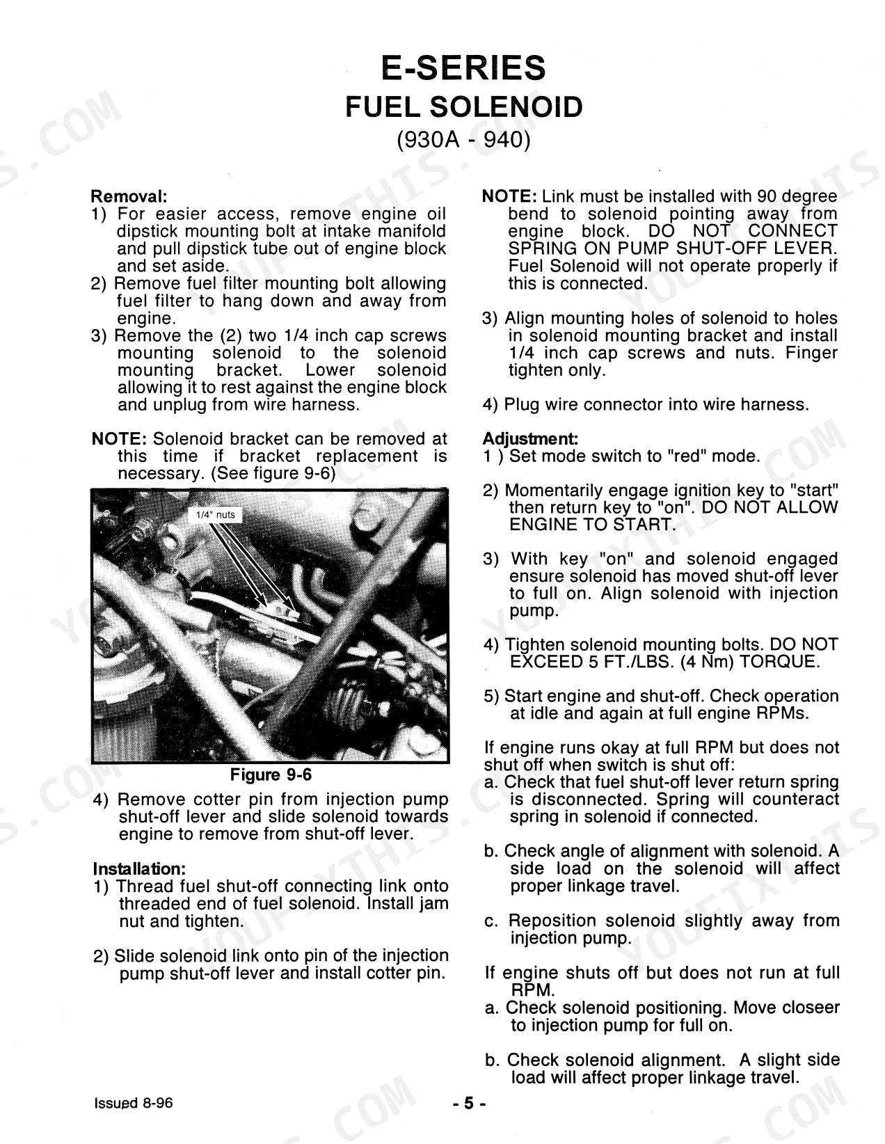
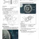
| E-Series Fuel Solenoid (930A - 940) | 128-129 | Removal (Remove: Engine Oil Dipstick, Fuel Filter Mounting Bolt, Solenoid Mounting Screws, Cotter Pin and Sprocket Nut) |
| E-Series Fuel Solenoid (920) | 130-131 | Removal (Remove Spring Clip and Disconnect Linkage, Remove Fuel Solenoid Mounting Bolts, Unplug and Remove Fuel Solenoid) |
| E-Series Electrical System Component Check | 132-133 | Mode Switch Test (Test in Red Mode, Continuity Test Terminal 2 to 3 and 4, Test in Green Mode, Continuity Test Terminal 2 to 1, Continuity Test Terminal 5 to 6, Switch Replacement) |
| E-Series Hydraulic System Explanation | 134 | Hydraulic Control Valve Main Relief, Work Port Relief in Lift Spool, Purpose of Work Port Reliefs, Electromagnetic Spool Locks |
Quick Reference Specifications
| Specification | Value | Page |
|---|---|---|
| 930, 940, 960 | ||
| Drive motor flanged lock nuts torque | 75 ft. lbs (102 Nm) | p. 78 |
| All Models | ||
| Neutral switch torque | 40 ft./lbs. (54.2 Nm) | p. 37 |
| Drive chain deflection | 1/8 inch (3.2 mm) with 12-15 lbs (5.4 - 6.8 kg) pull | p. 86 |
| Drive chain front adjustment nut torque | 210 ft. lbs. (285 Nm) | p. 86 |
| Parking Brake Engagement | 40 - 50 lbs. (18-23 kg) | p. 17 |
| Tire Pressure | 40-45 PSI (2.7-3.1 Bar) | p. 22 |
| 1/2 - 13, S.A.E. Grade 2, Plain Head Torque | 39 Foot - Pounds | p. 27 |
| 930 | ||
| Engine Displacement | 83 CID (1362 cc) | p. 6 |
| HP @ Governed RPM | 28 HP (20.6 kW) @ 2800 RPM | p. 6 |
| Hydraulic Pressure Relief | 2000 PSI (138 Bar) | p. 6 |
| 930, 940 | ||
| Cooling System Capacity | 6.5 qts. (6.1 L) | p. 6 |
| 960 | ||
| Fuel Tank Capacity | 20 gal. (75.7 L) | p. 8 |
Mustang 920–960 Common Problems This Manual Covers
Hard starting after fuel service
Air trapped after a filter change or fuel starvation makes the Yanmar-powered machines hard to prime and start. The Engine section covers the fuel system and cooling system troubleshooting.
Manual Section: Engine p. 99Weak or noisy drive motors
Wear in the drive motor or hydrostatic circuit leaves the machine weak or noisy under load. The Hydrostatic Drive System section covers charge pressure checks, the closed loop, and the piston pump and drive motor.
Manual Section: Hydrostatic Drive System p. 65Chaincase noise or metal in oil
Worn sprockets, chains, or bearings cause noise, vibration, and contamination in the chaincase. The Chain Case section covers the brake assembly and input drive shaft service and repair.
Manual Section: Chain Case p. 80Slow or weak hydraulics
Pump wear, a clogged filter, or a suction leak leaves lift and tilt slow or weak. The Hydraulic System section covers the pressure check and the lift and tilt circuit leak-down tests.
Manual Section: Hydraulic System p. 42Steering pull or drift from neutral
A T-bar or neutral centering issue makes the loader creep or pull when the controls are released. The Steering Controls section covers T-bar adjustments and neutral centering device service.
Manual Section: Steering Controls p. 34Hard to diagnose electrical or start fault
Intermittent starting and instrument faults trace to the wiring, starting circuit, or charging circuit. The Electrical System section provides the wiring diagram and starter and alternator disassembly.
Manual Section: Electrical System p. 111Frequently Asked Questions
Which models does this manual cover?
It covers the Mustang 930, 940, and 960 skid steer loaders built 1988 to 1991, plus the E-Series 920E, 930A, and 940E in a supplement, with Yanmar 3TN82E and 4TN82E and Isuzu 4JB1 diesel engines.
Does it include torque specifications?
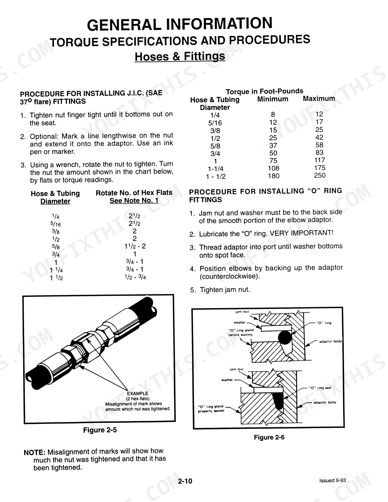
Yes. Standard and metric torque value specifications sit in the General Information section, covering fasteners, hoses, and fittings. p. 19
Can I check the hydrostatic drive with this manual?
Yes. The Hydrostatic Drive System section covers charge pressure checks and the relief valve tests used to trace weak or no drive. p. 65
Does it cover the E-Series interlock and solenoids?
Yes. Dedicated E-Series sections explain the electric solenoid spool locks, the fuel solenoid, and interlock troubleshooting for the 920E, 930A, and 940E. p. 121
What format is this Mustang 930 & variants manual in?
Delivered as a 134-page searchable PDF that downloads the moment you check out. Open it on a laptop, tablet, or phone and bring it straight to the shop floor.
Can I print specific sections of this Mustang 930 & variants Service Manual?
Yes. Print as many copies as you like, with no restrictions. Plenty of mechanics run off just the section they're working from and keep it at the bench.
Are hydraulic system diagrams in this Mustang 930 & variants Service Manual?
Full hydraulic system diagrams are included, covering circuits, valve locations, and hydraulic component specs for the Mustang 930 & variants.


Reviews
There are no reviews yet.