


This is the factory service manual for the Mustang MTL25 track loader, part number 908313, a 799 page reference covering the machine and its Yanmar engine variants. It spans the 3TNV, 4TNV, and 4TNE engine families used across production of this compact track loader.The manual is organized into General, Specifications, Machine Configuration, Hydraulic Units, and a large Troubleshooting section. You get drive and travel system service, frame and control work, HST pump and control valve repair, cylinder overhaul, servicing standards, and tightening torque tables, plus symptom based troubleshooting for the hydraulics and engine.It downloads as a PDF you can read on a computer, tablet, or phone, and print the pages you need at the bench. The file stays yours for future repairs.
What's Inside This Mustang MTL25 Manual
| System | Pages | Key Topics |
|---|---|---|
| Foot of the Page | 5-8 | - |
| I . General | 9-22 | Safety Precautions, Cautions During Disassembly and Assembly, Cautions During Removal and Installation of the Hydraulic Units, Cautions During Removal and Installation of Piping |
| Ii . Specifications | 23-44 | Names of Components, Specification Diagrams, Specification Tables, Mass Tables, Recommended Lubricants, Servicing Standards |
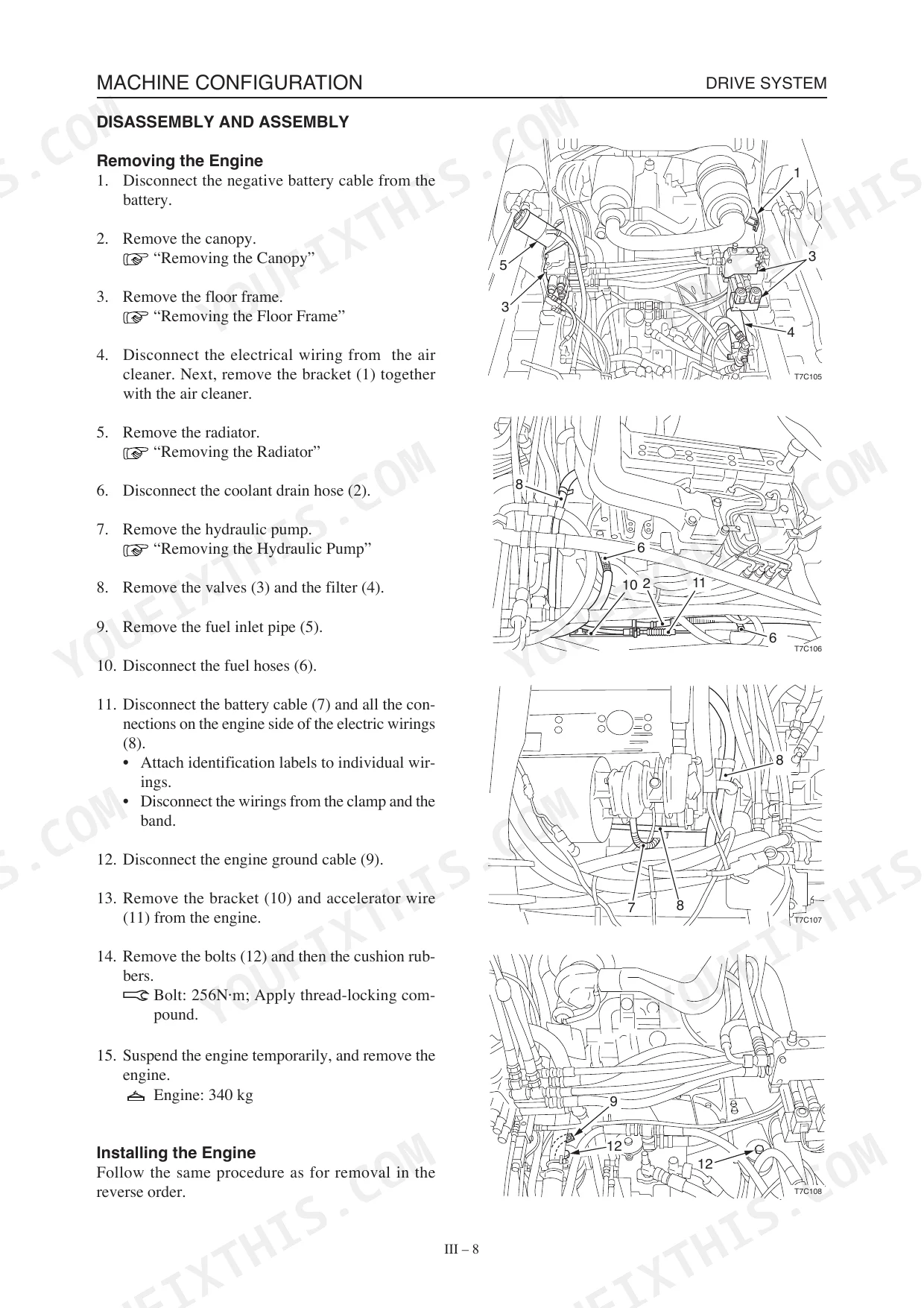
| Iii . Machine Configuration | 45-170 | Drive System, Travel System, Frame, Control System, Attachments, Hydraulic System |
| Iv . Hydraulic Units | 171-300 | HST Pump, Gear Pump, Control Valve, Pilot Valve, Self-Level Valve, Cylinders |
| V . Troubleshooting | 301-799 | 4Tne94/98/106, 3TNV/4TNV Series (Cover, History of Revision, Preface, Safety Labels, Contents, Tightening Torque for Bolts and Nuts, Back Cover) |
Quick Reference Specifications
| Specification | Value | Page |
|---|---|---|
| Hydraulic Air Bleeding Procedure (Cylinders) | Start engine at low idle, extend and contract all cylinders 4 or 5 times without going to stroke end. Run engine at high speed, then extend and contract all cylinders 4 or 5 times without going to stroke end. Set engine back to low idle, then extend and contract all cylinders 4 or 5 times to stroke ends. | p. 110 |
| Sprocket bolt torque | 241 N·m | p. 67 |
| Track roller A bolt torque | 241 N·m | p. 66 |
| Track roller B bolt torque | 156 N·m | p. 66 |
| Relay specifications (clearance, torque, replacement) | Not explicitly provided for individual relays; general electrical system checks are described. | p. 113 |
| Crawler Tension | 25~30 mm | p. 38 |
| General Service Parts Replacement Guideline | Replace all seals and cotter pins with new parts. | p. 17 |
| General Bolts and Nuts Torque (ISO Strength Category 10.9, General Tightening Points, M10 x 1.5) | 47.1 ±2.4 N·m | p. 21 |
| HST Pump Relief Valve Pressure Setting | 34.5 MPa | p. 28 |
| Travel Motor Parking Brake Torque | 314 N·m | p. 29 |
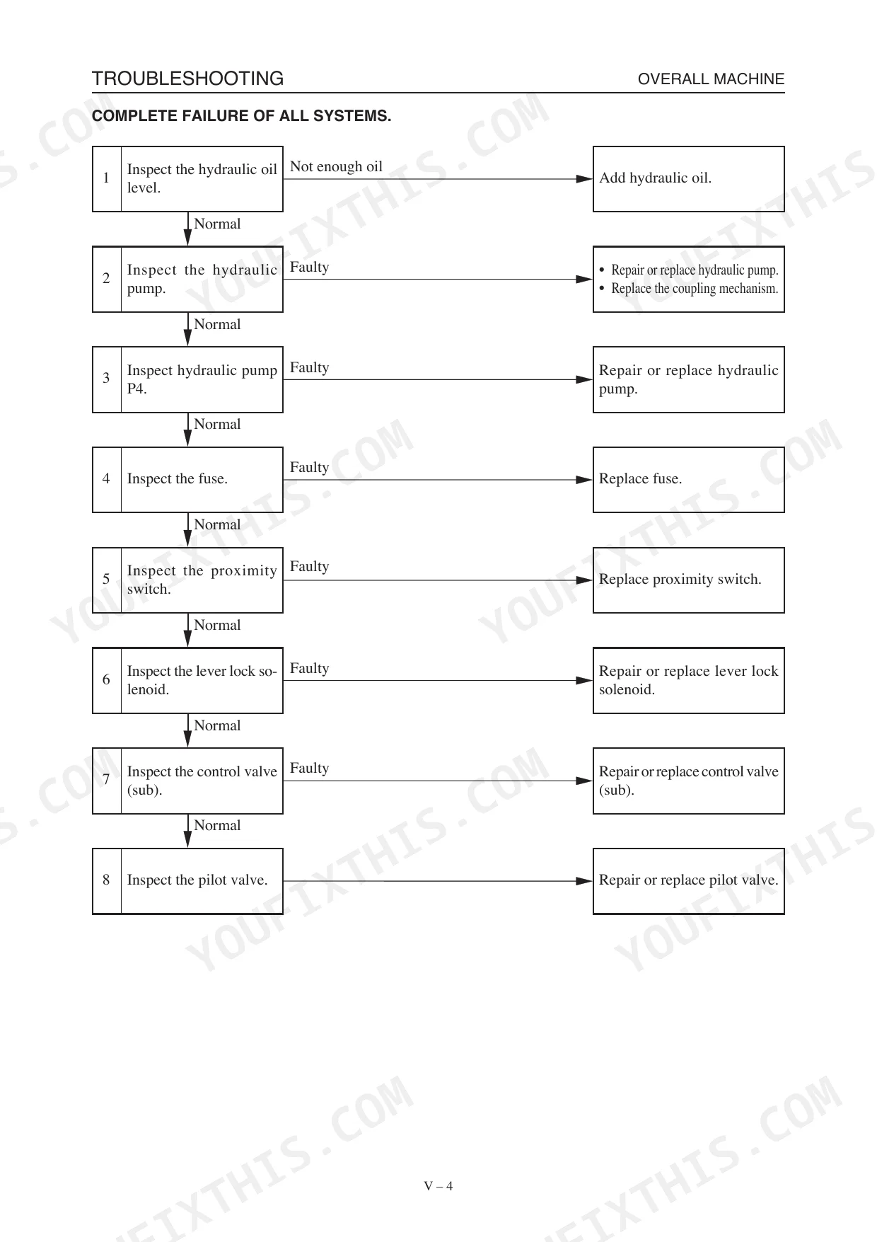
| Remedy for Not Enough Hydraulic Oil | Add hydraulic oil. | p. 304 |
| Remedy for Faulty Hydraulic Pump | Repair or replace hydraulic pump. Replace the coupling mechanism. | p. 304 |
Mustang MTL25 Common Problems This Manual Covers
Runs but no hydraulic operation
The machine cranks and runs but will not operate any hydraulic function, often from bad relays or an electrical control fault rather than a hydraulic failure. The troubleshooting section works through these no-operation symptoms.
Manual Section: V. Troubleshooting p. 301Poor steering in high speed mode
Sluggish or poor steering response can appear when maneuvering in high speed mode, and shifting to slow mode often restores control. The machine configuration section covers the control and travel systems.
Manual Section: III. Machine Configuration p. 45Track tension or rubber track wear
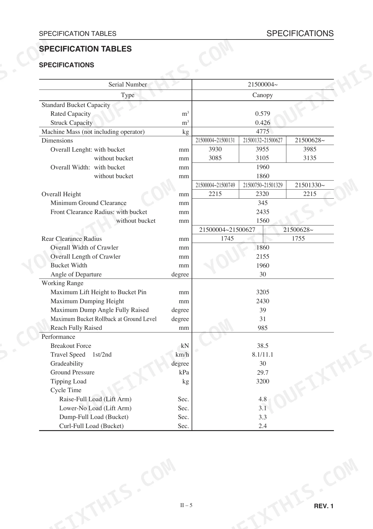
Loose or worn rubber tracks affect traction and ride quality. The specifications set crawler tension at 25 to 30 mm and give the track adjuster set load for correct tensioning.
Manual Section: II. Specifications p. 23Hydraulic unit or HST pump fault
Weak or lost hydraulic power can trace to the HST pump, gear pump, or control valve. This section covers removal, disassembly, and reassembly of each hydraulic unit.
Manual Section: IV. Hydraulic Units p. 171Air in cylinders after service
After opening a hydraulic circuit, trapped air causes spongy or erratic cylinder movement. The manual gives a bleeding procedure of cycling the cylinders several times at idle and high speed without reaching stroke end.
Manual Section: III. Machine Configuration p. 45Engine runs poorly or stalls
Hard starting, rough running, or stalling points to fuel, air, or engine mechanical issues. The engine troubleshooting chapter covers the Yanmar 4TNE and TNV series used in this loader.
Manual Section: 4TNE94/98/106(T) p. 332Frequently Asked Questions
Which machine does this manual cover?
It covers the Mustang MTL25 compact track loader, part number 908313, in a single 799 page PDF. Engine troubleshooting spans the Yanmar 3TNV, 4TNV, and 4TNE families fitted to this machine.
Does it include torque specifications?
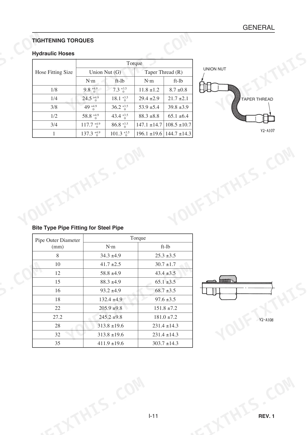
Yes. The Specifications section lists servicing standards and tightening torque, including 241 N.m for the sprocket and track roller A bolts and 156 N.m for track roller B. p. 23
Does it cover hydraulic troubleshooting?
Yes. The Troubleshooting section diagnoses faults such as a machine that runs but will not operate any hydraulic function, tracing likely causes and remedies. p. 301
How is the manual delivered?
You download the PDF right after purchase, so there is nothing to ship and the manual is available immediately.
What do I get after purchasing this Mustang MTL25 manual?
Immediate download of the complete 799-page searchable Service Manual. Access it on any device — laptop at your desk or phone in the field.
Are there any print restrictions on this Mustang MTL25 manual?
Yes, print as many copies as you want — there are no restrictions. Many mechanics print the section they need and bring it to the shop floor.
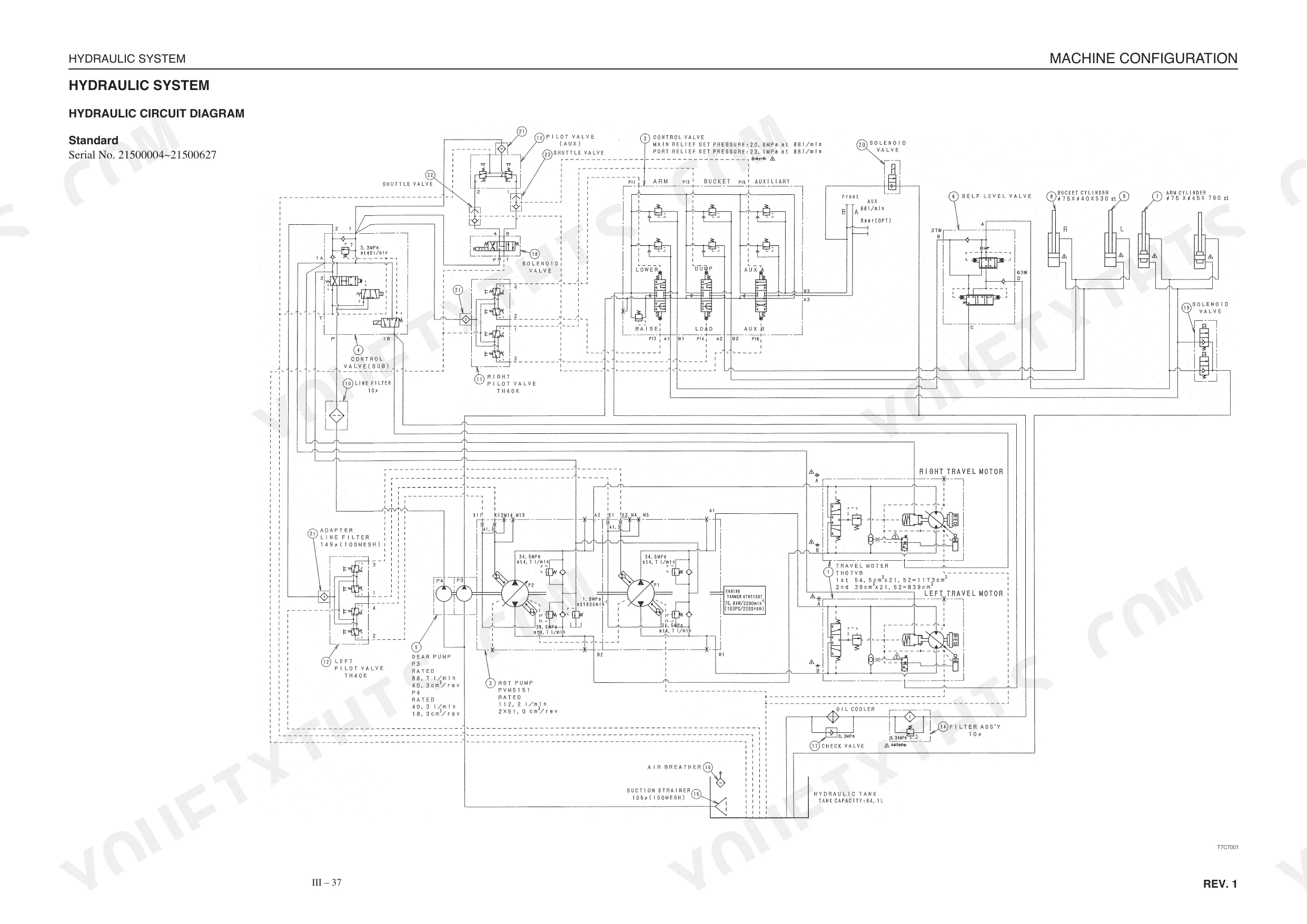
Can I find hydraulic circuit diagrams in this Mustang MTL25 manual?
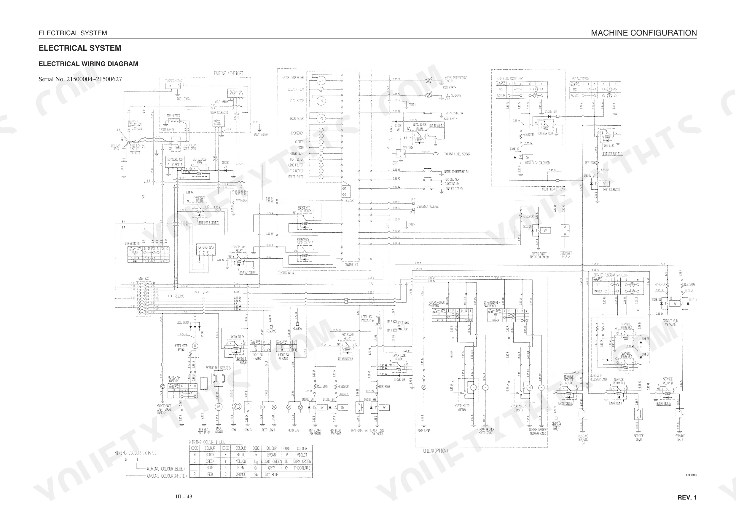
Yes — complete hydraulic schematics with flow diagrams, valve configurations, and pressure specifications are included.


Reviews
There are no reviews yet.