


This is the factory service manual for the Mustang 642 and 844 telehandlers, 341 pages covering both machines and their John Deere 4045T engine. The 642 lifts up to 6600 lbs and the 844 up to 8000 lbs, and the book documents service for both models together.Sections walk through engine removal and installation, electrical schematics and troubleshooting, steering, transmission, front and rear axles, and the full hydraulic system including the pump, cylinders, and boom. You also get torque charts, fluid capacities, decal locations, and step by step boom and telescoping chain procedures.It downloads as a PDF that opens on a computer, tablet, or phone. Print the pages you need for the shop, or keep the whole file on hand for reference during a repair.
What's Inside This Mustang 642, 844 Manual
| System | Pages | Key Topics |
|---|---|---|
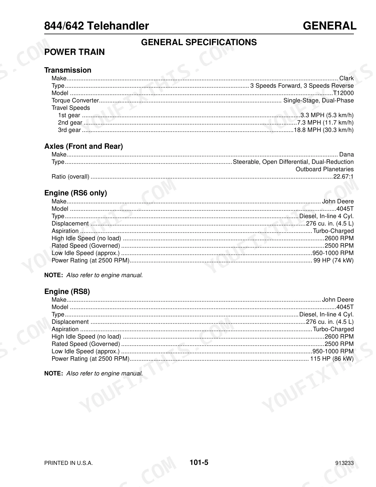
| Safety & Machine Identification | 5-17 | Personal Safety Information and Decal Locations, General Information and Specifications, Safety Rules and Reminders, Decal Locations, Roll Over Protective Structure, Sae Fastener Torque Chart, Metric Fastener Torque Chart, Standard Torque Data for Hydraulic Tubes and Fittings, Indicator and Operation Symbols, Fluid Capacities and Types |
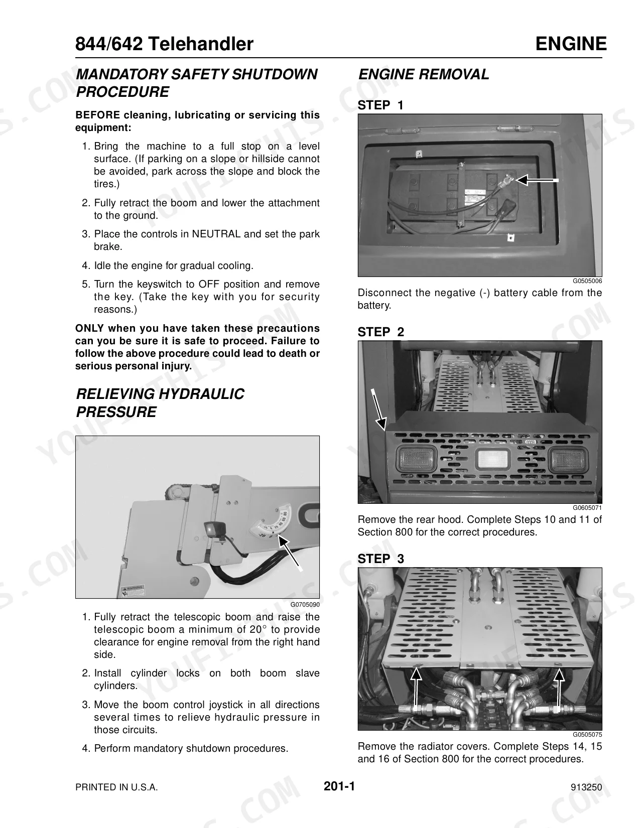
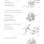
| Engine | 33-56 | Engine Removal, Engine Installation, Special Torque Values, Relieving Hydraulic Pressure |
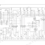
| Electrical System & Battery | 57-88 | Instrument Panel Bulb Replacement, Electrical Schematics, Battery Removal, Battery Installation |
| Steering & Drivetrain | 89-136 | Steering Control Valve Removal and Installation, Transmission Removal and Installation, Rear Axle Removal and Installation, Front Axle Removal and Installation, Relieving Hydraulic Pressure |
| Hydraulic Schematics & Pump | 137-192 | Hydraulic Schematics, Testing & Adjustment Procedures, Hydraulic Specifications, Hydraulic Pump Removal, Hydraulic Pump Installation |
| Frame Leveling & Tilt Cylinders | 193-208 | Frame Leveling Cylinder Removal and Installation, Tilt Cylinder Removal and Installation, Relieving Hydraulic Pressure |
| Hydraulic Cylinder Repair | 209-220 | Cylinder Disassembly, Cylinder Assembly, General Information |
| Stabilizer Cylinders | 221-240 | Stabilizer Cylinder Removal and Installation, Stabilizer Cylinder Disassembly, Stabilizer Cylinder Assembly, Relieving Hydraulic Pressure |
| Slave & Lift Cylinders | 241-264 | Slave Cylinder Removal and Installation, Lift Cylinder Removal and Installation, Lift Cylinder Adjustment, Lift Cylinder Eccentric Pin Adjustment |
| Boom Extend Cylinder & Boom Assembly | 265-284 | Boom Extend Cylinder Removal and Installation, Boom Assembly Removal and Installation, Relieving Hydraulic Pressure |
| Boom Chains & Sections | 285-324 | Leaf Chain Adjustment and Maintenance, Inner Boom Section Removal and Installation, Telescoping Boom Double Chain Roller Bearing, Telescoping Boom Single Chain Roller Bearing Replacement, Intermediate Boom Section Removal and Installation |
| Hood and Cover | 325-341 | Front Hood Removal, Front Hood Installation, Rear Hood Removal, Rear Hood Installation, Radiator Cover Removal |
Every system also includes mandatory safety shutdown procedure.
Quick Reference Specifications
| Specification | Value | Page |
|---|---|---|
| Wheel Nut Torque | 450 ft.-lbs. (610 Nm) | p. 119 |
| Recommended Tire Type | 13.00 x 24 G2 12-ply | p. 26 |
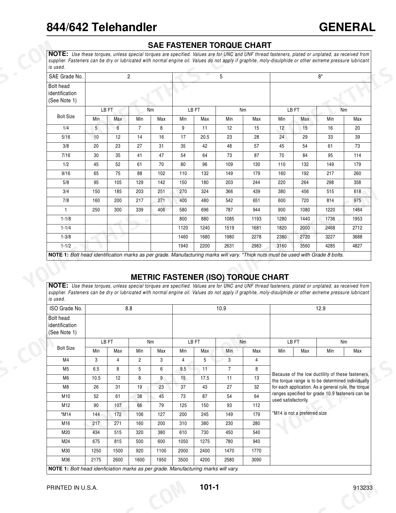
| Hydraulic Tube and Fitting Torque (Thread Size 7/16-20) | 9 to 12 lb-ft (12 to 16 Nm) | p. 20 |
| Hydraulic Tube and Fitting Torque (Thread Size 1/2-20) | 12 to 15 lb-ft (16 to 20 Nm) | p. 20 |
| Seal Replacement | Install new seals (no specific numerical value) | p. 215 |
| Hydraulic Filter Type | Remote, 10 Micron, Replaceable Element | p. 24 |
| Hydraulic Filter Rated Flow | 100 GPM (371 L/min) | p. 24 |
| Battery Type | One - 950 CCA Low-Maintenance Type, Group Size 4 DLT | p. 25 |
| Battery Terminal Tightness | Clean and tight (no specific numerical torque value) | p. 86 |
| Engine Crankcase Capacity (4045T John Deere) | 14.0 qts (13.3 L) | p. 22 |
| Hydraulic System Reservoir Capacity | 47.0 gal (178 L) | p. 22 |
| Main Control Valve Relief Pressure | 3000 PSI (207 bar) | p. 24 |
Mustang 642, 844 Common Problems This Manual Covers
Boom is weak, slow, or loses power
Weak lift or a boom that loses power during operation usually points to hydraulic leaks, low fluid, air in the system, worn seals, or a failing pump. The hydraulic troubleshooting and test procedures track down the fault.
Manual Section: Hydraulic Schematics, Troubleshooting Testing & Adjustment Procedures p. 137Hard starting or excessive smoke
Difficult starting or heavy exhaust smoke often comes from low battery voltage, poor connections, a fuel system fault, or a clogged filter. The engine section covers removal, installation, and special torque values.
Manual Section: Engine p. 33Erratic or failing electrical controls
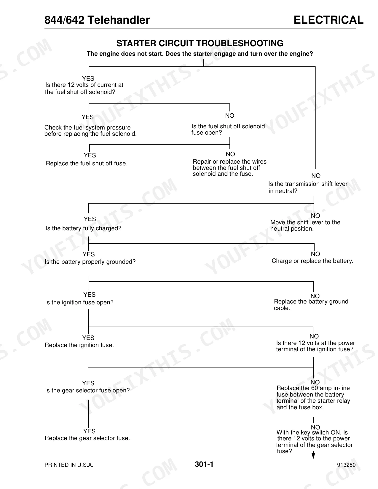
Controls that behave erratically or drop out intermittently are commonly caused by battery corrosion, loose connections, or wiring faults. The electrical schematics and troubleshooting procedures help isolate the circuit.
Manual Section: Electrical Schematics, Troubleshooting Testing & Adjustment Procedures p. 57Boom binding or abnormal wear
A boom that binds, wears unevenly, or functions poorly often reflects neglected lubrication or worn components. Boom assembly removal and installation is documented in full.
Manual Section: Boom Assembly Removal and Installation p. 273Leaf chain wear or slack
The single and double leaf chains that carry the telescoping boom stretch and wear over time. This section covers leaf chain adjustment and maintenance to keep the boom operating safely.
Manual Section: Single and Double Leaf Chain Adjustment p. 285Hydraulic cylinder leaks or seal wear
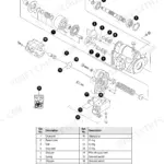
Drifting or leaking cylinders point to worn seals or internal damage. The hydraulic cylinder repair section covers disassembly, seal replacement, and reassembly.
Manual Section: Hydraulic Cylinder Repair p. 209Frequently Asked Questions
Which machines does this manual cover?
It covers the Mustang 642 and 844 telehandlers, part number 913250, with the John Deere 4045T engine, in one 341 page PDF.
Does it include torque specifications?
Yes. The General Information and Specifications section provides SAE and metric fastener torque charts and hydraulic tube and fitting data, and wheel nut torque is 450 ft-lbs. p. 17
Does it cover hydraulic troubleshooting?
Yes. The Hydraulic Schematics, Troubleshooting, Testing and Adjustment Procedures section covers schematics, hydraulic specifications, and test procedures for the system. p. 137
How is the manual delivered?
You download the PDF straight after checkout, so there is no shipping wait and the file stays yours for future repairs.
What do I get after purchasing this Mustang 642, 844 manual?
Checkout delivers a 341-page searchable PDF, downloadable right away. Open it on a laptop, tablet, or phone and take it straight to the shop floor.
Are there any print restrictions on this manual?
Yes. The PDF carries no DRM, so print any page or section you need for the shop. It works with any standard printer.
Can I find hydraulic circuit diagrams in this Mustang 642, 844 manual?
Yes. Full hydraulic schematics are included, with flow diagrams, valve configurations, and pressure specifications.

Reviews
There are no reviews yet.