


This is the factory service manual for the Mustang 2109 skid steer loader with the Cummins 4B4.5T engine, part number 917229. It is a 238 page PDF covering assembly and disassembly, removal and installation, adjustment, testing, and troubleshooting for the machine.Sections cover specifications, safety, lubrication, the mainframe, wheel drives, controls, the hydrostatic and hydraulic systems, the engine, and the electrical system with its instrument panels and interlock module. You get pressure tests, torque values such as the 170 ft-lbs engine mount figure, capacities, and step by step component procedures.It downloads as a PDF you can open on a computer, tablet, or phone, and print the pages you need for the shop. Cummins engine internals are referenced to Cummins service for deeper engine work.
What's Inside This Mustang 2109 Manual
| System | Pages | Key Topics |
|---|---|---|
| A | 231 | Actuator Group Components 4-13, Additional Safety Reminders 2-1, Air Cleaner and Exhaust Components 9-4, Air Cleaner Assembly Removal and Installation 9-7 |
| D | 232 | Operation - Right and Left Instrument Panels 10-1, Dimensional Specifications 1-2, Dome Light Bulb Replacement 10-25, Drive Chain Adjustment 5-2 |
| E | 233 | Electric Power-A-Tach Attachment Bracket Components 4-14, Electric ROPS Lift Assist Pump - Removal and Installation 10-27, Electrical Lights Components 10-23 |
| F | 233 | Fan Belt Replacement 9-13, Fan Shroud Adjustment 9-16, Fan Shroud Removal and Installation 9-15, Floor Cover / Battery Cover - Removal and Installation 4-27 |
| G | 233 | Glow Control Module Test 10-12, Glow Solenoid Test 10-12, Grease Fitting Locations 3-3 |
| H | 234 | Hand Throttle Adjustment - Hand/Foot 6-43, Hand Throttle Removal and Installation 6-40, Hand Throttle Tension Adjustment 6-42, Hand/Foot Control Handle Assembly 6-13 |
| I | 235 | Interlock Control Module Test 10-14, Interlock Control Module Truth Table 10-15, Introduction 1-2 |
| J | 235 | Joystick Control Handle Assembly 6-19, Joystick Control Models - Lift and Tilt Components 6-5 |
| K | 235 | Keyswitch on Position Sequence 10-3 |
| L | 236 | Lift Arm Components 4-15, Lift Arm Removal and Installation 4-16, Lift Cylinder Components 8-25, Lift Cylinder Removal and Installation 8-23, Lift Cylinder Test 8-16 |
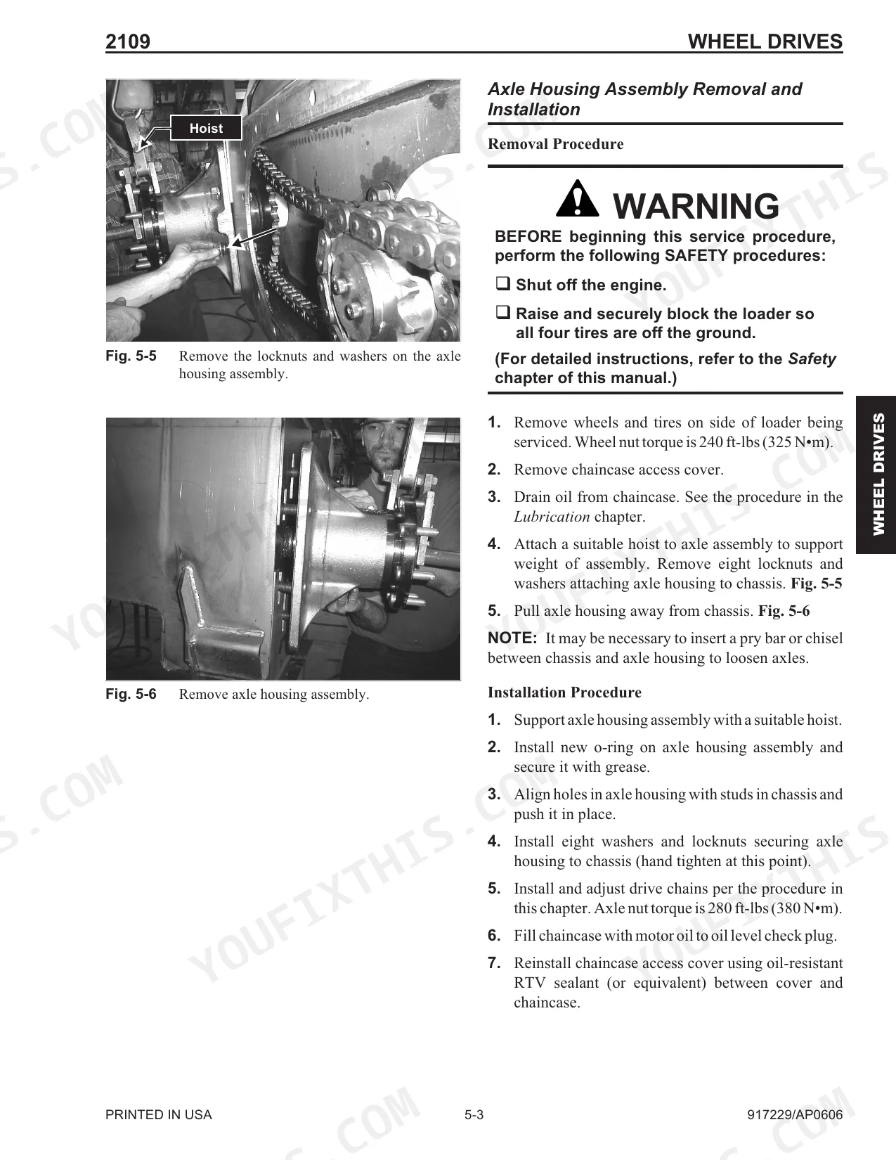
| M | 236 | Mainframe Chapter (Air Duct Louver Replacement 4-9, Air Duct Removal and Installation 4-9, All-Tach, Power-A-Tach Attachment Bracket Removal and Installation 4-12, Control Console Removal and Installation 4-25, Crossmember Removal and Installation 4-28, Engine Access Covers - Removal and Installation 4-1, Floor Cover/Battery Cover - Removal and Installation 4-27, Fuel Sensor Removal and Installation 4-30, Introduction 4-1, Lift Arm Removal and Installation 4-16, Links and Lift Arm Bushing Replacement 4-24, Rear Bumper Removal and Installation 4-33, Rear Grille Bracket, Latch and Grille - Removal and Installation 4-32, Rear Grille Removal and Installation 4-31, Rear Link Removal and Installation 4-21, Restraint Bar Removal and Installation 4-10, ROPS Rear Window Removal and Installation 4-9, ROPS/FOPS Removal and Installation 4-6, Seat Removal and Installation 4-8, Seat Slide Replacement 4-8, Timing Link Removal and Installation 4-23) |
| N | 237 | Neutral Centering Device Adjustment 6-22 |
| O | 237 | Oil Filter Element Removal and Installation 9-6 |
| P | 237 | Pivot Tube Removal and Installation - T-Bar, Hand/Foot and Dual Hand 6-20, Power Relay Test 10-11, Pressure Tests, System and Load-Sense Standby 8-11 |
| R | 237 | Radiator and Cooler Components 9-5, Rear Bumper Removal and Installation 4-33, Rear Grille Bracket, Latch and Grille Removal and Installation 4-32 |
| S | 238 | Safety Chapter (Additional Safety Reminders 2-1, Liftarm Support Device 2-3, Liftarm Support Device Disengagement 2-4, Liftarm Support Device Engagement 2-3, Loader Lowering Procedure 2-7, Loader Raising Procedure 2-7, Mandatory Safety Shutdown Procedure 2-2, Relieving Hydraulic Pressure 2-6, ROPS, Lowering 2-5, Raising 2-4, Signal Words 2-1) |
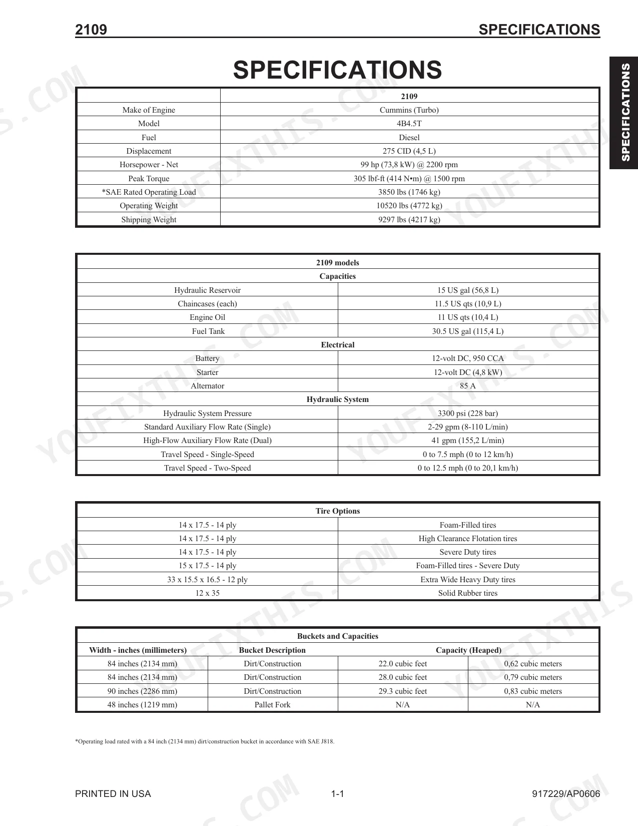
Quick Reference Specifications
| Specification | Value | Page |
|---|---|---|
| Engine Mounts Torque | 170 ft-lbs (230 N•m) | p. 192 |
| Tilt Cylinder Capscrew Torque | 80 ft-lbs (108 N•m) | p. 143 |
| Engine Oil Filter Replacement Interval | 500 hours of service | p. 18 |
| Engine Oil Filter Installation Turn | 3/4 turn | p. 178 |
| Coolant Mixture | 50% water, 50% ethylene glycol | p. 17 |
| Hydrostatic Pump Mechanical Centering Adjustment Pressure | 1000 psi (70 bar) | p. 85 |
| Engine Displacement | 4.5 L | p. 7 |
| Engine Net Horsepower | 99 hp | p. 7 |
| Hydraulic Reservoir Capacity | 15 US gal | p. 7 |
| Engine Oil Capacity | 11 US qts | p. 7 |
| Hydraulic System Pressure | 3300 psi | p. 7 |
| Axle Housing Locknuts Torque | 280 ft-lbs | p. 56 |
Mustang 2109 Common Problems This Manual Covers
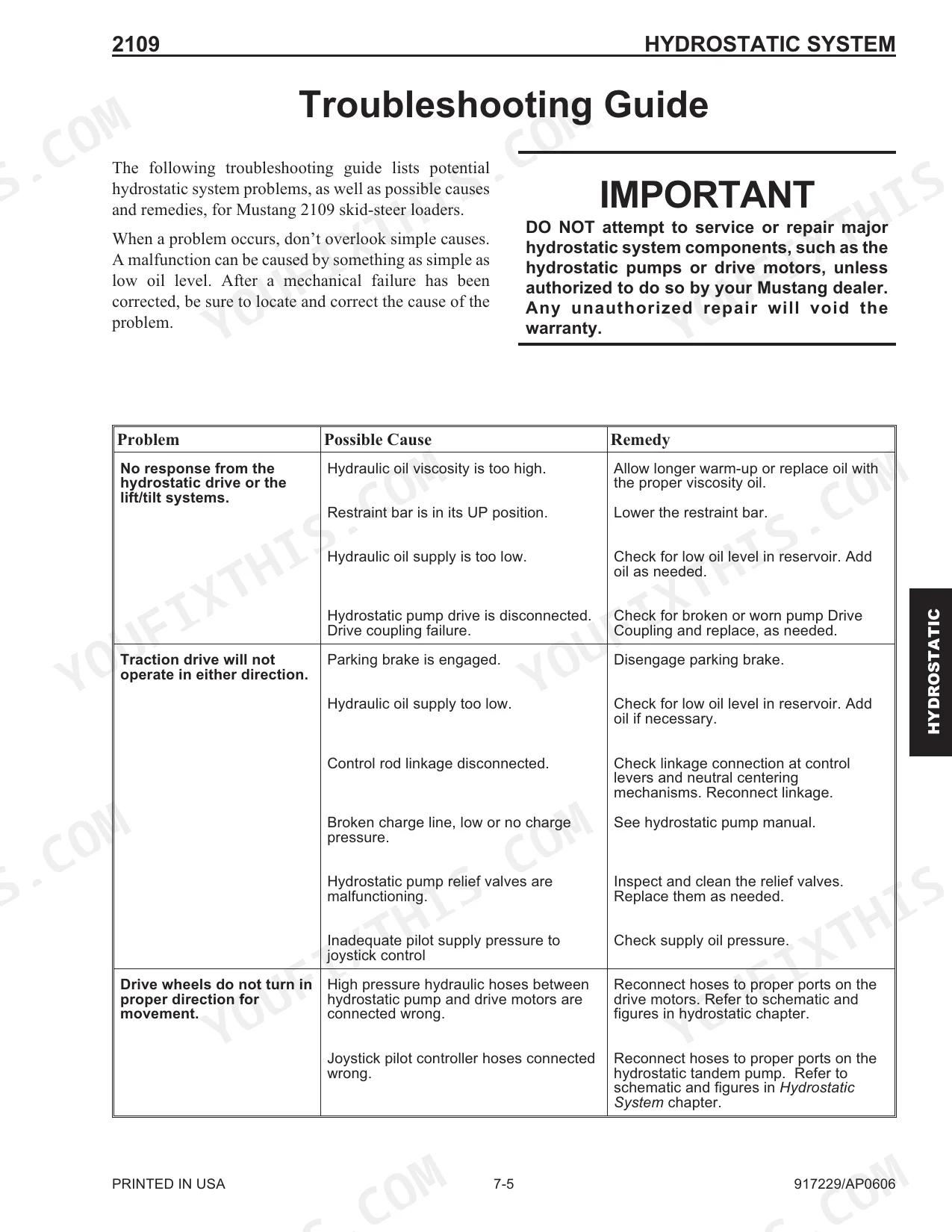
Hydraulic functions slow or erratic
Slow or jerky hydraulic response often traces to low fluid, leaks, worn seals, or a control valve fault. Charge pressure testing and adjustment help pin down the cause.
Manual Section: Charge Pressure Test and Adjustment p. 119Loader movement uneven or noisy
Uneven or stalled attachment movement can come from loose control connections or a control valve issue. Control valve removal, disassembly, and reassembly are covered step by step.
Manual Section: Control Valve Removal and Installation p. 160Engine overheating
Overheating usually stems from low coolant, a clogged radiator, or restricted airflow. The manual specifies a 50/50 water and ethylene glycol mix and covers cooling system draining.
Manual Section: Cooling System Drain Procedures p. 22Hard starting or no start
Starting trouble on the Cummins 4B4.5T can be a weak battery, loose connections, or a clogged air or fuel filter. Air cleaner service and replacement are documented.
Manual Section: Air Cleaner Assembly Removal and Installation p. 181Weak or jerky drive response
Inconsistent drive can result from control system faults, bad safety switch inputs, or wiring problems. Control handle removal and adjustment procedures address the linkage side.
Manual Section: Control Handle Removal and Installation p. 70Warning or instrument panel lights
Unexpected instrument panel warnings can be a sensor, relay, or switch input rather than a real failure. The electrical section describes right and left instrument panel operation and testing.
Manual Section: Description of Operation - Right and Left Instrument Panels p. 197Frequently Asked Questions
Which machine does this manual cover?
It covers the Mustang 2109 skid steer loader with the Cummins 4B4.5T engine, part number 917229, in a single 238 page PDF.
Does it include torque specifications?
Yes. It lists values such as 170 ft-lbs for the engine mounts and 350 ft-lbs for the cylinder rod locknut, along with axle and wheel nut torque figures. p. 192
Does it cover the hydraulic and hydrostatic systems?
Yes. It includes charge pressure testing and adjustment, control valve service, and pressure tests for the load-sense standby circuit. p. 119
How is the manual delivered?
You download the PDF right after purchase, so there is nothing to ship and the file stays yours for future repairs.
How will I receive this Mustang 2109 Service Manual?
Checkout delivers a 238-page searchable PDF, downloadable right away. Read it on a laptop, tablet, or phone and carry it straight to the shop floor.
Can I print this Mustang 2109 manual?
No restrictions at all. Print individual pages, full chapters, or the entire manual. The PDF is completely unlocked.
Are there wiring harness diagrams in this Mustang 2109 manual?
Yes. You'll find full electrical schematics with wire routing diagrams, connector identification, and circuit descriptions.


Reviews
There are no reviews yet.