


This is the factory service manual for the Mustang 2095 and 2105 skid steer loaders, 204 pages covering both models in a single PDF. The 2095 runs a Yanmar 4TNE106 rated at 90 hp, while the 2105 uses the turbocharged 4TNE106T at 110 hp, and the book documents both machines section by section.You get the full repair reference: hydrostatic drive and hydraulic system troubleshooting with pressure tests, wheel drive and drive chain service, control handle adjustment, electrical diagnosis with the interlock control module truth table, and engine servicing. Torque values, capacities, and step by step removal and installation procedures run throughout.It is a downloadable PDF you can read on a phone, tablet, or computer, or print the pages you need for the shop bench.
What's Inside This Mustang 2095, 2105 Manual
| System | Pages | Key Topics |
|---|---|---|
| Introduction | 2-6 | Tire Options, Buckets and Capacities, Dimensional Specifications, Safety, General Information, Signal Words, Additional Safety Reminders |
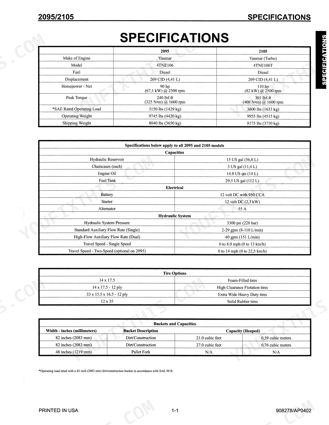
| Specifications | 7-8 | Tire Options, Buckets and Capacities, Dimensional Specifications, Capacities, Electrical, Hydraulic System |
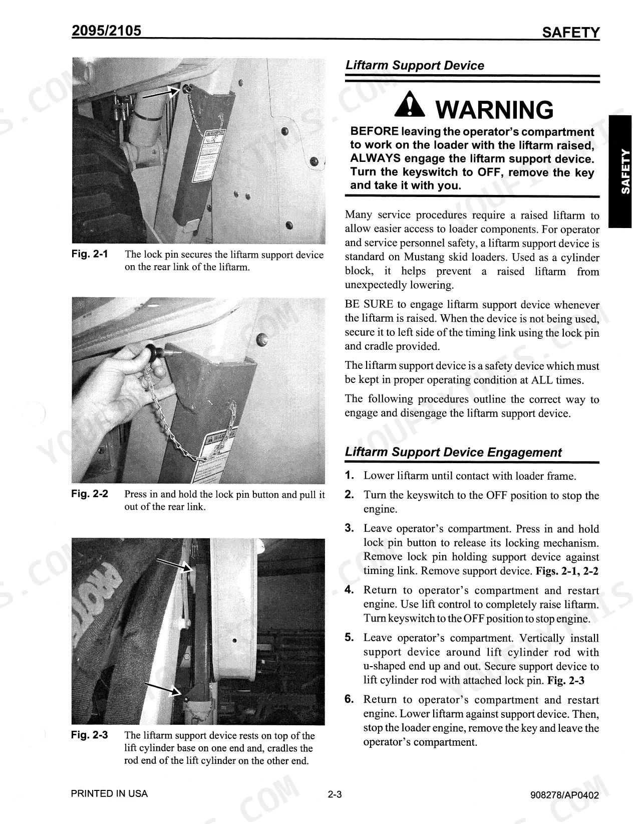
| Safety | 9-16 | - |
| Lubrication | 17-20 | Hydraulic Oil Reservoir, Crankcase Oil, Chaincases, Grease Fitting Locations, Cooling System Drain Procedures |
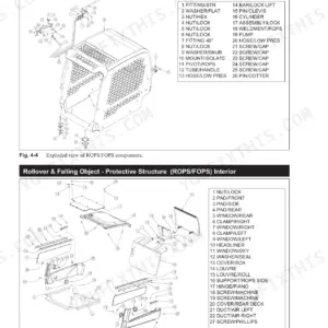
| Mainframe | 21-46 | Introduction, Engine Access Covers - Removal and Installation, Rollover Protective Structure Removal and Installation, Seat Removal and Installation, Seat Slide Replacement |
| Wheel Drives | 47-54 | Introduction, Drive Chain Adjustment, Axle Housing Assembly Removal and Installation, Drive Chain Removal and Installation, Axle and Wheel Bearing Disassembly and Assembly |
| Controls | 55-90 | Introduction, Control Handle Removal and Installation, Control Handle Position Adjustment, Control Handle Tracking Adjustment, Traction Controls, Dual T-Bar Control Handle Assembly |
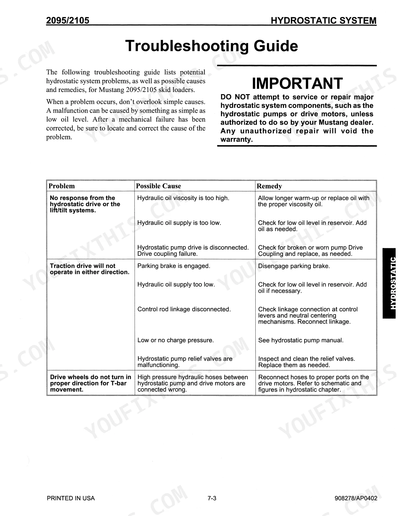
| Hydrostatic System | 91-102 | Introduction, Troubleshooting Guide, Charge Pressure Test and Adjustment, Hydrostatic Pump Relief Valves, Hydrostatic Pump Removal and Installation |
| Hydraulic System | 103-148 | Introduction, Troubleshooting Guide, Pressure Tests, System and Load-Sensing Standby, Tilt Cylinder Test, Self-Leveling Valve Test, Lift Cylinder Test |
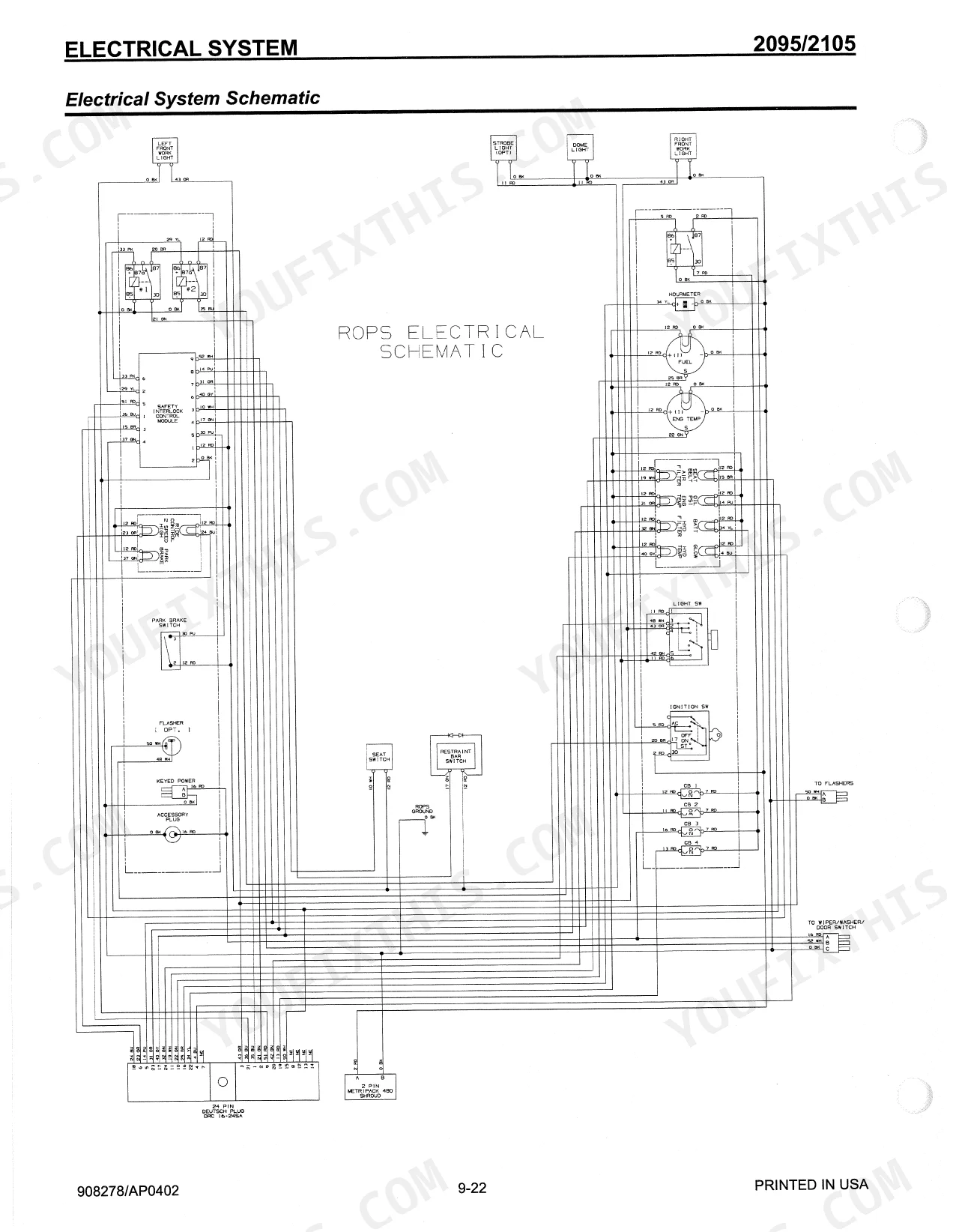
| Electrical System | 149-172 | Introduction, Operation - Right and Left Instrument Panels, Troubleshooting Guide, Module and Relay Test and Operation, Interlock Control Module Truth Table |
| Engine | 173-192 | Introduction, Troubleshooting Guide, Oil Filter Element Removal and Installation, Air Cleaner Assembly Removal and Installation, Air Filter Element Removal and Installation |
Quick Reference Specifications
| Specification | Value | Page |
|---|---|---|
| Axle housing locknuts torque | 280 ft-lbs (380 N•m) | p. 49 |
| Wheel nut torque | 180 ft-lbs (244 N•m) | p. 49 |
| Tilt cylinder pivot pin capscrew torque | 80 ft-lbs (108 N•m) | p. 29 |
| Multi-Tach hitch components torque | 240 FT-LB | p. 30 |
| Air filter element replacement condition | when restriction gauge shows red zone or instrument panel light comes on | p. 179 |
| Hydraulic Reservoir Capacity | 15 US gal (56,8 L) | p. 17 |
| Hydraulic oil type | Mobil DTE 15M, or Petro-Canada Premium HVI60, or equivalent which contains anti-rust, anti-foam, and anti-oxidation additives & conforms to ISO VG46 | p. 17 |
| Hydraulic oil filter element replacement condition | when restriction indicator light on left instrument panel comes on or rear hydraulic filter service indicator reads red | p. 119 |
| Hydraulic filter element tightening | Hand tighten until gasket contacts filter head, then turn element another 3/4 turn | p. 120 |
| Fan belt deflection | 1/2" (13 mm) under a load of 20 lbs (90 N) | p. 184 |
| Drive chain deflection | ½" @ 20 lbs (13 mm @ 89 N) | p. 48 |
| Drive chain minimum deflection | 1½" (13 mm) | p. 48 |
Mustang 2095, 2105 Common Problems This Manual Covers
Machine will not move or drives weakly
One or both drive sides feel weak, jerky, or stall under load, often from low hydraulic fluid, a clogged filter, air in the system, or worn drive components. The hydrostatic troubleshooting guide walks through charge pressure tests and relief valve checks.
Manual Section: Hydrostatic System p. 91Loader arms rise unevenly or stall
Lift arms that respond slowly or stall usually trace to low hydraulic fluid, a restricted filter, pump wear, or a valve fault. Pressure tests plus the lift, tilt, and self-leveling valve tests isolate the cause.
Manual Section: Hydraulic System p. 103Chain slack, rattling in the drivetrain
Excessive chain slack, clanking, or rattling in the undercarriage is a common skid steer complaint. This section covers drive chain adjustment, removal, and axle and wheel bearing service.
Manual Section: Wheel Drives p. 47Engine overheats or runs poorly
Overheating or weak engine performance often comes from low coolant, a blocked air filter, or fuel filter neglect. Engine troubleshooting and filter service procedures are covered here.
Manual Section: Engine p. 173Warning lights or interlock faults
Instrument panel warnings or an interlock that blocks operation can stem from a module, relay, or sensor fault. The troubleshooting guide and interlock control module truth table help trace the circuit.
Manual Section: Electrical System p. 149Hydraulic fluid or filter service
Weak overall operation is frequently a fluid or filter issue. The lubrication section covers the hydraulic oil reservoir, fill procedures, and service points.
Manual Section: Lubrication p. 17Frequently Asked Questions
Which machines does this manual cover?
It covers the Mustang 2095 and 2105 skid steer loaders in one PDF. The 2095 uses a Yanmar 4TNE106 rated at 90 hp and the 2105 uses the turbocharged 4TNE106T rated at 110 hp.
Does it include torque specifications?
Yes. Torque values appear throughout, including axle housing locknuts at 280 ft-lbs and wheel nut torque at 180 ft-lbs in the Wheel Drives section, plus cylinder and engine mount figures. p. 47
Does it cover hydraulic system troubleshooting?
Yes. The Hydraulic System section includes a troubleshooting guide, pressure tests, load-sensing standby, and individual tilt, lift, and self-leveling valve tests. p. 103
How do I get the manual after buying?
You download the PDF straight after checkout, so there is no wait for shipping and you keep the file for future reference.
What do I get after purchasing this Mustang 2095, 2105 manual?
A 204-page Service Manual in searchable PDF format, available the moment you complete checkout. Open it on a computer, tablet, or phone, with no shipping wait.
Can I print this Mustang 2095, 2105 manual?
Yes, print as many copies as you want; there are no restrictions. Many mechanics print just the section they need and take it to the shop floor.
Are there wiring harness diagrams in this Mustang 2095, 2105 manual?
Yes. Full electrical schematics are included, with wire colors, connector locations, and circuit descriptions.


Reviews
There are no reviews yet.