


This is the factory service manual for the Mustang ME6003 compact excavator, part number 918175, covering the machine built around the Yanmar 4TNV98-VNS EPA Tier II diesel. The 180 page PDF is the same shop reference a dealer technician works from, with a searchable text layer and 191 built in bookmarks for fast navigation.Inside you get engine, hydraulic, and electrical coverage: torque values, fluid and filter intervals, track tension figures, and the full set of hydraulic circuit and wiring harness diagrams for both wiring versions. Whether you are chasing a no start, restoring lost hydraulic power, or tracing a wiring fault, the procedures and specifications are laid out for real repair work.Owners, independent mechanics, and restorers can download it instantly and print any page they need at the bench.
What's Inside This Mustang ME6003 Manual
| System | Pages | Key Topics |
|---|---|---|
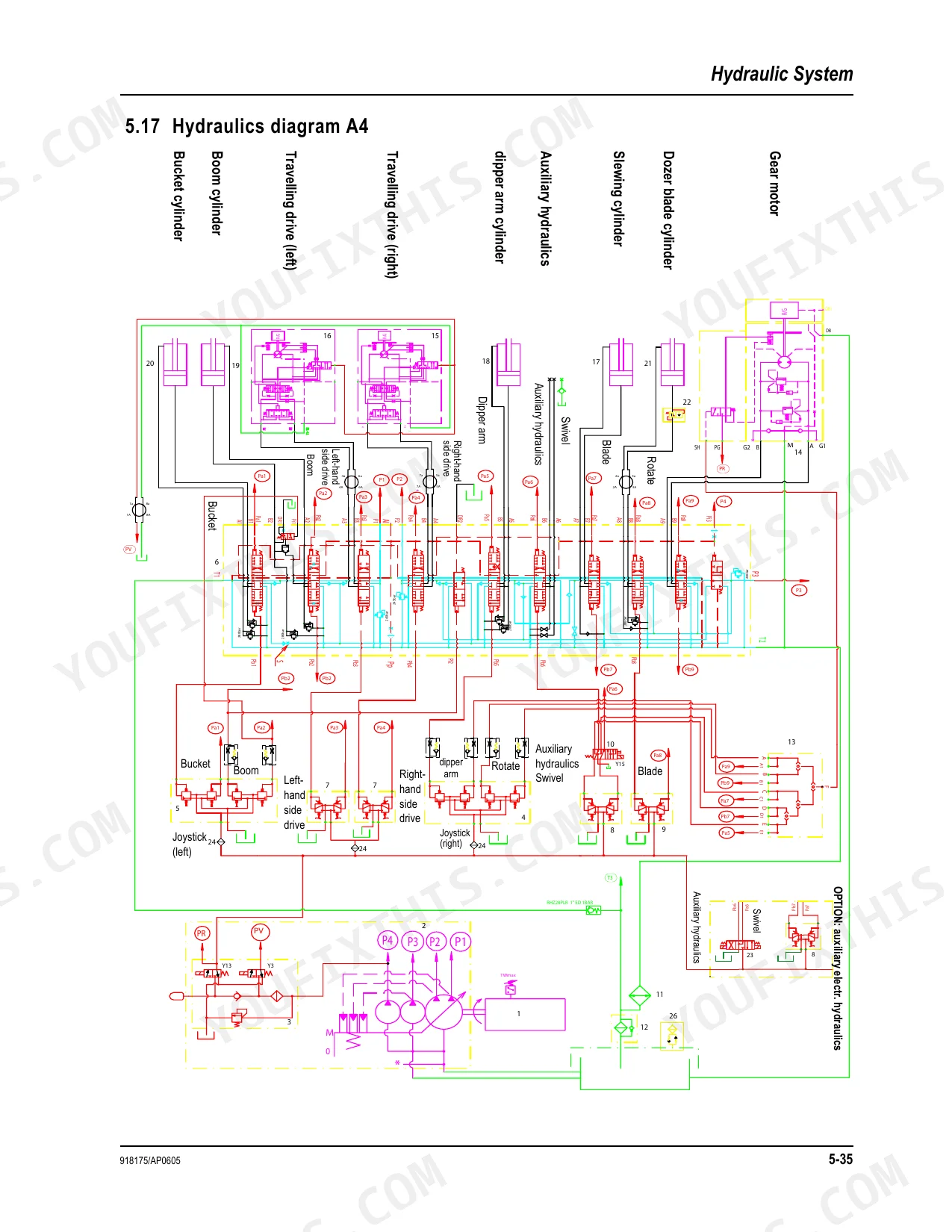
| Hydraulics Diagram | 131 | Gear Motor, Dozer Blade Cylinder, Slewing Cylinder, Auxiliary Hydraulics, Dipper Arm Cylinder, Travelling Drive |
| Main Valve Block Diagram | 132 | Pilot Control Lines, Main Control Lines, Pump/tank Lines, Bucket Cylinder, Boom Cylinder, Gear Motor |
| Hydraulics Diagram with 3rd Control Circuit (Option) | 133 | Gear Motor, Dozer Blade Cylinder, Slewing Cylinder, Auxiliary Hydraulics, Dipper Arm Cylinder, 3rd Control Circuit |
| Main Valve Block Diagram with 3rd Control Circuit (Option) | 134-142 | Pilot Control Lines, Main Control Lines, Pump/tank Lines, 3rd Control Circuit, Bucket Cylinder, Gear Motor |
| Wiring Harness 1000109629: Cab Roof | 143 | Loudspeaker, Radio, Wiper Motor, Front Roof Light, Interior Light, Rotating Beacon |
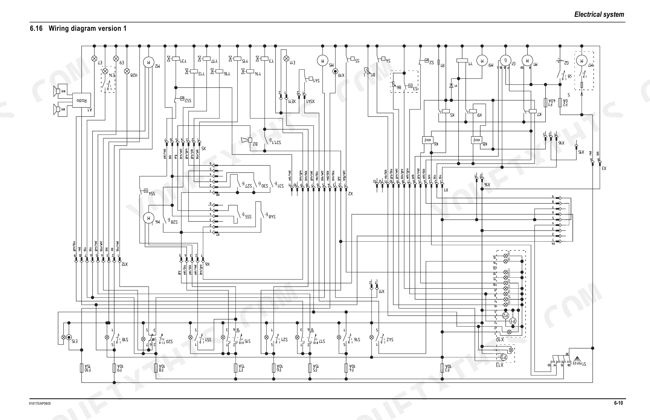
| Wiring Diagram Version 1 | 144 | Fuses, Relays, Switches, Indicators, Alternator, Starter |
| Wiring Diagram Version 1: Legend | 145 | Fuses, Relays, Switches, Indicators, Alternator, Pilot Valves |
| Wiring Diagram Version 1 | 146 | Fuses, Relays, Switches, Indicators, Alternator, Starter |
| Wiring Diagram Version 2: Legend | 147 | Fuse, Relay, Switch, Indicator, Solenoid Valve, Wiring Connection |
| Wiring Diagram Version 2 | 148 | Fuses, Relays, Switches, Indicators, Solenoids, Wiring Connections |
| Wiring Harness 1000109624 (Legend): Engine - Chassis | 149 | Alternator, Starter, Main Fuse, Cut-Off Solenoid, Fuel Pump, Solenoid Valve |
| Wiring Harness 1000109624: Engine - Chassis | 150 | Main Fuses, Relays, Alternator, Fuel Pump, Solenoid Valves, Wiring Connections |
| Wiring Harness 1000109630 (Legend) Version 1: Switches | 151 | Pre-Heating Start Switch, Drive Interlock Connection, Indicator Connection, Boom Working Light Switch, High Speed Switch, Fuse |
| Wiring Harness 1000109630 Version 1: Switches | 152 | Switches, Indicators, Fuses, Relays, Wiring Connections, Accessory Power Socket |
| Wiring Harness (Legend) Version 2: Switches A4 | 153 | Pre-Heating Start Switch, Drive Interlock Connection, Indicator Connection, Warning Buzzer, Boom Working Light Switch, Solenoid Valve |
| Wiring Harness Version 2: Switches | 154-180 | Switches, Indicators, Fuses, Relays, Wiring Connections, Warning Buzzer |
Quick Reference Specifications
| Specification | Value | Page |
|---|---|---|
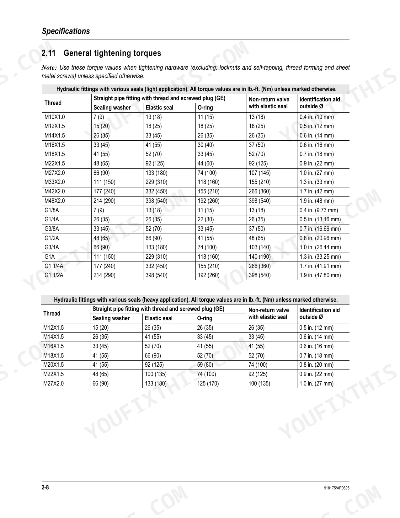
| General tightening torques note | Use these torque values when tightening hardware (excluding locknuts, and self-tapping, thread-forming, and sheet metal screws) unless specified otherwise. | p. 36 |
| Fuel filter replacement interval | Every 250 Hours | p. 50 |
| Hydraulic oil tank capacity | 22 gals. (83 L) | p. 31 |
| Track tension deflection | 3/4”-1” (20-25 mm) | p. 66 |
| Hydraulic hoses replacement interval | Every six years | p. 80 |
| Battery terminals grease specification | FINA Marson L2 | p. 67 |
| Fuse F1 (Main fuse box with relays) rated current | 40 Amp | p. 33 |
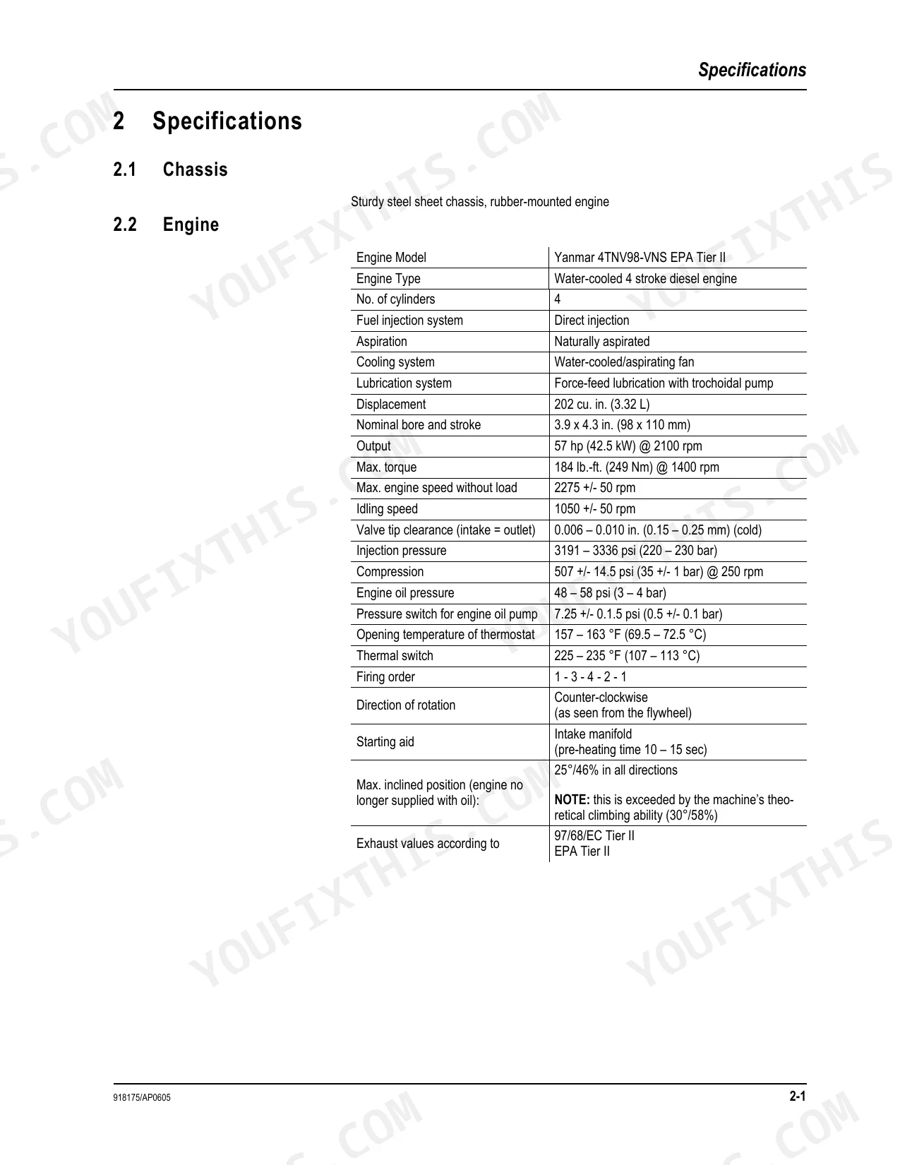
| Pressure switch for engine oil pump | 7.25 +/- 0.1.5 psi (0.5 +/- 0.1 bar) | p. 29 |
| Main pressure limiting valve P1, P2 | 3553±44 psi (245±3 bar) | p. 31 |
| Thermal switch operating temperature | 225 – 235 °F (107 – 113 °C) | p. 29 |
| Engine Output | 57 hp (42.5 kW) @ 2100 rpm | p. 29 |
| Engine Max. torque | 184 lb.-ft. (249 Nm) @ 1400 rpm | p. 29 |
Mustang ME6003 Common Problems This Manual Covers
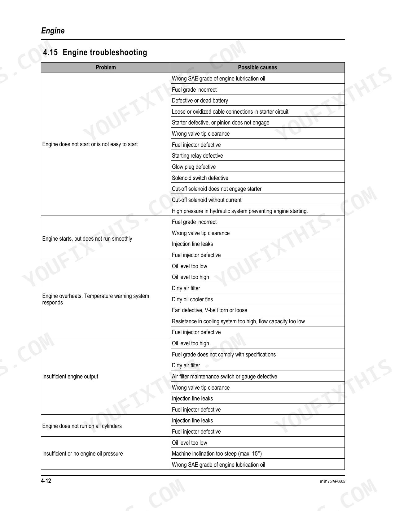
Hard starting or no start
Cranks weakly or will not fire, often from a fuel delivery restriction, weak battery, or poor connection at the starter or cut off solenoid. The engine to chassis harness diagram maps the alternator, starter, and fuel pump wiring so you can trace the circuit end to end.
Manual Section: 6.22 Wiring harness 1000109624: engine - chassis p. 150Weak or slow hydraulic response
Boom, bucket, or dipper functions feel sluggish or lose force under load, commonly from low or contaminated oil, a leaking line, or a pressure setting that has drifted. The main valve block diagram shows the pilot and main control lines, and the main pressure limiting valve P1, P2 is set to 3553 plus or minus 44 psi (245 plus or minus 3 bar).
Manual Section: 5.20 Main valve block diagram p. 132Track pulls to one side
Uneven travel or a machine that crawls off line usually points to track tension out of spec or unequal travel drive output. The hydraulics diagram covers the travelling drive and gear motor circuit; correct track tension is 20 to 25 mm (3/4 to 1 in.) of deflection.
Manual Section: 5.19 Hydraulics diagram p. 131Intermittent warning lights or blown fuses
Flickering indicators, dead accessories, or a repeatedly failing fuse trace back to loose terminals, a tired relay, or a shorted circuit. Wiring diagram version 1 lays out the fuses, relays, switches, and indicators so you can isolate the branch that keeps tripping.
Manual Section: 6.16 Wiring diagram version 1 p. 144Auxiliary attachment circuit trouble
Machines fitted with the optional third control circuit can lose flow to a hydraulic attachment or fail to switch functions. The third control circuit hydraulics diagram shows the auxiliary, slewing, and dozer blade lines needed to diagnose it.
Manual Section: 5.21 Hydraulics diagram with 3rd control circuit (option) p. 133Dozer blade or slew cylinder drift
A blade that settles or a house that creeps under load usually means worn cylinder seals or a leaking valve section. The main valve block diagram with the third control circuit maps the bucket, boom, and gear motor lines feeding those cylinders.
Manual Section: 5.22 Main valve block diagram with 3rd control circuit (option) p. 134Frequently Asked Questions
Which machine and engine does this manual cover?
It covers the Mustang ME6003 compact excavator, part number 918175, powered by the Yanmar 4TNV98-VNS EPA Tier II diesel rated at 57 hp (42.5 kW). The PDF runs 180 pages.
Does it include the wiring diagrams?
Yes. It contains full wiring harness and diagram coverage for both wiring versions, including the engine to chassis harness legend that identifies the alternator, starter, main fuse, and fuel pump connections. p. 149
Are the hydraulic schematics included?
Yes. The hydraulics diagram maps the gear motor, dozer blade cylinder, slewing cylinder, dipper arm cylinder, auxiliary hydraulics, and travelling drive, which is what you need for pressure and flow diagnosis. p. 131
What is the main hydraulic relief pressure?
The main pressure limiting valve P1, P2 is set to 3553 plus or minus 44 psi (245 plus or minus 3 bar). The specification is listed in the machine data section. p. 31
What do I get after purchasing this Mustang ME6003 manual?
Download starts the moment payment clears. The full 180-page searchable Service Manual is yours to open on a laptop, tablet, or phone right there in the shop.
Can I print this Mustang ME6003 manual?
Absolutely. No DRM or copy protection. Print the whole manual or just the pages you need. Any home or office printer works.
Does this Mustang ME6003 Service Manual cover the hydraulic system?
Full hydraulic system diagrams are included, covering circuits, valve locations, and hydraulic component specs for the Mustang ME6003.


Reviews
There are no reviews yet.