


![New Holland G110.2 G110.2 6WD Tier 2 Repair Manual [Grader]](https://youfixthis.com/wp-content/uploads/2012/02/Manual_Download-300x300.jpg)
Included 2 Factory PDF Manuals:
New Holland TV140 Tractor Repair Manual. Remove and install, assembly and disassembly, service, maintenance, inspection, repair, overhaul, troubleshooting, tune-ups procedures.
New Holland TV140 Tractor Operators Manual. Procedures for operating, troubleshooting, maintenance, specifications.
Detailed step by step illustrations, instructions, diagrams. Digital PDF format, searchable and bookmarked, very clean, sharp images.
PDF Manual:
2790+ pages
Instant download – You will receive a link for download on your email immediately after payment.
Lifetime access to download (by request)
Compatible with Windows, IOS, Android and other systems
Searchable Text and Built-in index for instant information search
Bookmarks
Printable – pages or entire manual
Zoomable – detailed exploded diagrams, picture
Models
New Holland TV140 Bi-directional Tractor
Contents
Operators Manual:
General information
Operation
Lubrication and Maintenance
Troubleshooting
Specifications
First 50-hour service
Index
Repair Manual:
GENERAL INFORMATION
Precautionary Statements
Safety Precautions
General Considerations
Tractor Identification
Engine Identification
Service Techniques
Minimum Hardware Tightening Torques
Standard Torque Data
Recommended Lubricants and Coolants
Recommended Sealants
ENGINE
Chapter – Engine Systems
AIR INDUCTION SYSTEM
Specifications
Bolt Torque Specifications
Special Tools
Air Induction System – Description and Operation
Introduction
Component Operation
Troubleshooting
Turbocharger Boost Testing
Air Induction System – Removal and Repair of Components
Turbocharger Intake Tube
Turbocharger Outlet Tube
Air Filter Housing, Precleaner, and Air Induction Scoop
Turbocharger
Repair Time Schedule
EXHAUST SYSTEM
Specifications
Bolt Torque Specifications
Exhaust System – Description of Operation
Exhaust System Component Removal and Repair
Exhaust Muffler and Stack
Repair Time Schedule
ENGINE
Engine Specifications
Torque Values
Special Tools
Description and Operation
Introduction
Cylinder Head Assembly
Camshaft Assembly
Connecting Rods
Pistons
Manifolds
Cylinder Block Assembly
Timing Gears
Lubrication System
Troubleshooting
Dynamometer Engine Testing
Dynamometer Engine Break In
Compression Test
Engine Overhaul
Introduction
Engine Removal
Engine Disassembly
Engine Component Disassembly, Inspection, and Assembly
Front Timing Gears, Oil Pan, Camshaft, and Valve Tappets (Lifters)
Pistons and Connecting Rods
Crankshaft and Main Bearings
Oil Pump and Sump Tube
Oil Cooler/Filter Support Assembly
Flywheel
Engine Assembly
Engine Installation
Repair Time Schedule – Engine Overhaul
COOLING SYSTEM
Bolt Torque Specifications
Special Tools
Cooling System Description and Operation
Introduction
Individual Component Operation
Cooling System Troubleshooting
Cooling System Testing
Cooling System Tests
Cooling System – Removal and Repair of Components
Radiator
Thermostat
Cooling Fan (North American Models)
Cooling Fan and Viscous Clutch (International Models)
Fan Belt Tensioner
Water Pump
Repair Time Schedule – Cooling System
Chapter – Fuel System
Specifications
TV140 Fuel Injection Pump Test Plan
Special Tools
Fuel System – Description and Operation
Introduction
Fuel Injection Pump
Engine Shutoff
Troubleshooting
Injector Nozzle Testing
Fuel System Service
Bleeding The Fuel Injection System
Fuel Injectors
Bosch VE Fuel Injection Pump
Electric Lift Pump
Fuel Sedimenter
Fuel Filter
Fuel Tanks
Crossover Tube
Cold Start System – North American Models
Cold Start System – International Models
Throttle Cable
Repair Time Schedule – Fuel System
TRANSMISSIONS
Chapter – Splitter Box, Hydrostatic Drive, and Drivelines
Introduction
Orientation
Splitter Box
Hydrostatic Drive Description
Specifications
Torque Specifications
Special Tools
Safety
Power Flow
Description of Operation
Splitter Box Description
Splitter Box Gear Sets
Hydrostatic and Hydraulic System Components
Hydrostatic Drive Description
Moving a Disabled Tractor
Troubleshooting and Testing
Pressure Testing
Range Select Control Switch and Valve
Overhaul
Removal and Installation
Introduction
Splitter Box
Auxiliary Pump
Disassembly, Inspection, and Repair
Auxiliary Drive Housing
Auxiliary 3/4′ Couplers
Articulation Joint Drive Shafts
Upper Drive Shaft
Engine Power Input Shaft
Lower Drive Shaft
Splitter Box Power Input (Top) Shaft
Splitter Box Power Output (Bottom) Shaft
Engine-end Axle Drive Shaft
Splitter Box
Tapered Bearing End Play Check and Adjustment
Hydrostatic Motor
Hydrostatic Pump
FNR Lever Cables
Repair Time Schedule
ENGINE-END AXLE
Chapter – Engine-End Axle
Specification
Axle Shaft Preload
Axle Shaft Spacer Selection Table
Differential Bearing Preload
Differential Bearing Shim Table
Drive Pinion Preload
Drive Pinion Spacer Table
Tightening Torques
Special Tools
Introduction
Drive Path
Drive Pinion
Differential
Planetary Assembly
Axle Shaft and Trumpet Housing
Differential Lock
Troubleshooting
Disassembly and Repair
Trumpet/Axle Disassembly
Planetary Disassembly
Planetary Inspection
Planetary Reassembly
Planetary Ring Gear Removal
Planetary Ring Gear Installation
Trumpet/Axle Inspection
Trumpet/Axle Reassembly
Pinion Gear Removal
Pinion Gear Disassembly
Pinion Gear Inspection
Center Housing Inspection
Pinion Gear Reassembly
Pinion Bearing Preload
Drive Pinion Spacer Table
Pinion Gear Installation
Differential Disassembly
Differential Inspection
Differential Reassembly
Differential Bearing Preload
Differential Bearing Shim Table
Differential Lock Internal Operating Components Overhaul
Differential Lock Vah/e and Tube Removal
Differential Lock Vah/e and Tube Inspection
Differential Lock Vah/e and Tube Installation
Oscillating Components
Rear Trunnion Inspection
Rear Trunnion Installation
Front Trunnion Removal
Front Trunnion Inspection
Front Trunnion Installation
Diff Lock Switch Removal
Diff Lock Switch Inspection
Diff Lock Switch Installation
Apply Solenoid and Valve Removal
Apply Solenoid and Valve Inspection
Apply Solenoid and Valve Installation
Breather Removal
Breather Inspection
Breather Installation
Repair Time Schedule
CAB AND AXLE
Chapter – Cab-End Axle
Specifications
Torque Specifications
Special Tools
Introduction
Overview
Description of Operation
Troubleshooting
Overhaul
Repair Time Schedule
POWER TAKE-OFF
Chapter – Cab-End PTO
Specifications
Special Tools
Description of Operation
Cab-End PTO Clutch Control Valve Operation
Cab-End Output Drive
Electrical Operation
Cab-End PTO Electrical Circuit
Troubleshooting
Disassembly and Repair
Preliminary Procedures
Cab-End PTO Clutch
Cab-End PTO Shafts and Gears
PTO Switch
Repair Time Schedule
Chapter – Engine-End PTO
Specifications
Special Tools
Description of Operation
Electrical Operation
Engine-End PTO Electrical Circuit
Engine-End Output Drive
Clutch and Brake Pressure Apply
Lubrication Flow
Breather Lines
Troubleshooting
Testing PTO Gearbox Drain Pump Flow
Disassembly and Repair
Preliminary Procedures
Engine-End PTO Gearbox Overhaul
PTO Transfer Shaft and Coupler
Clutch Pressure Apply Hose
Lube Motor
Lube Circuit Hose
Breather and Hose
Apply Solenoid and Valve
Brake
PTO Switch
Repair Time Schedule
BRAKES
Specifications
Special Tools
Introduction
Overview
Description of Operation
Troubleshooting and Testing
Adjustments
Removal and Installation of Components
Brake Disc Components
Foot Pedal Linkage
Master Cylinder
Reservoir
Hose – Reservoir To Master Cylinder
Tubes – Pressure Supply
Park Brake Lever
Park Brake Cables and Links
Brake Pedal Switch
Park Brake Switch
Repair Time Schedule
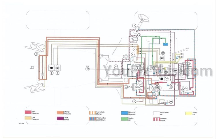
HYDRAULIC SYSTEMS
Specifications
Special Tools
Description and Operation
Auxiliary Hydraulics
Component Identification
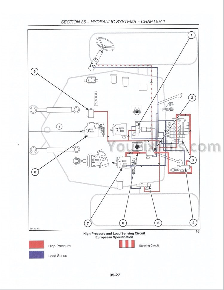
Hydraulic Circuits
Description of Operation
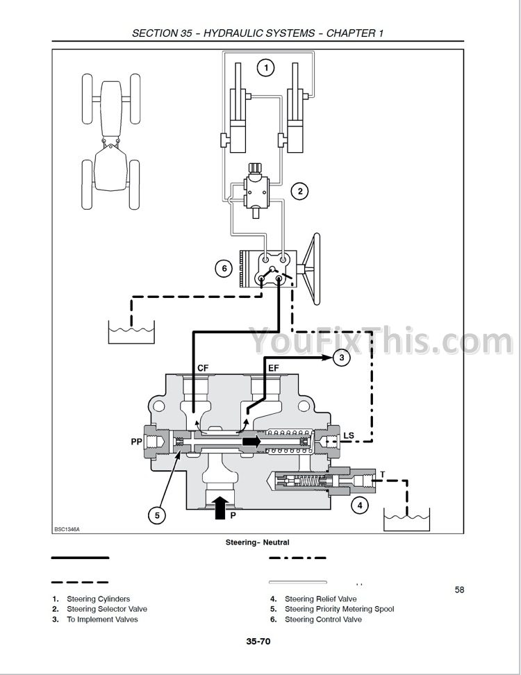
Steering Control Valve
Troubleshooting and Testing
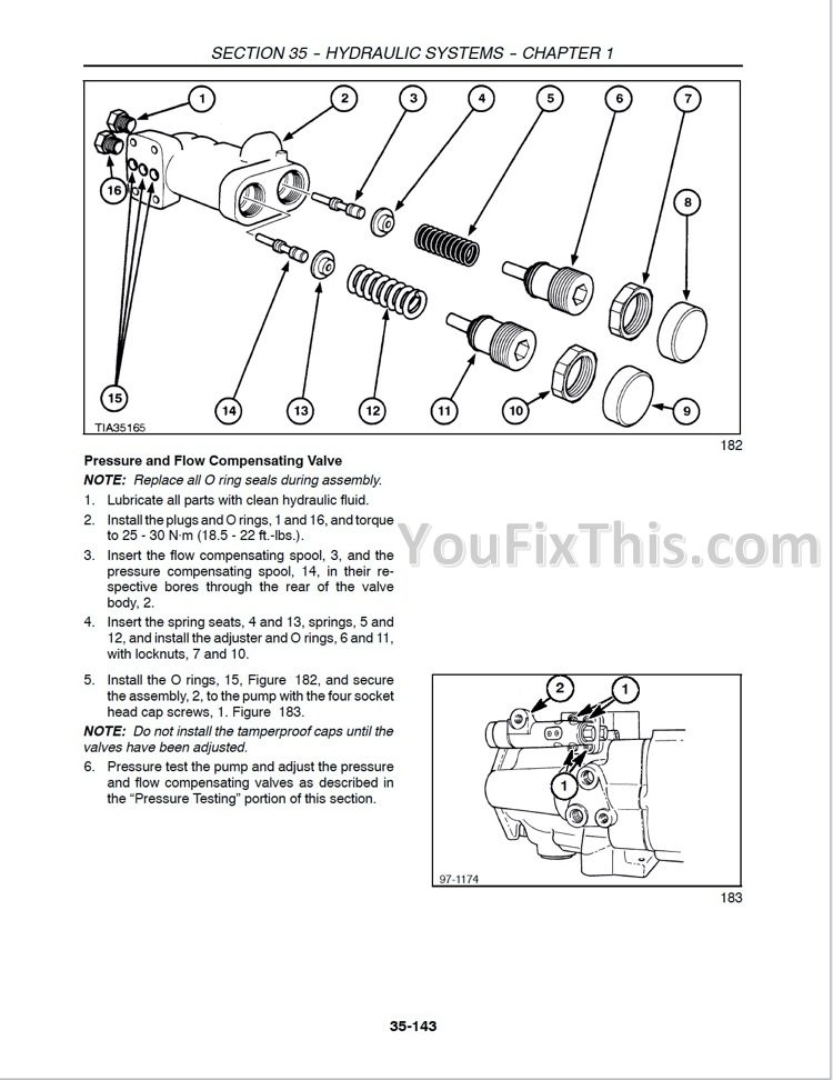
Disassembly and Repair
Implement Pump
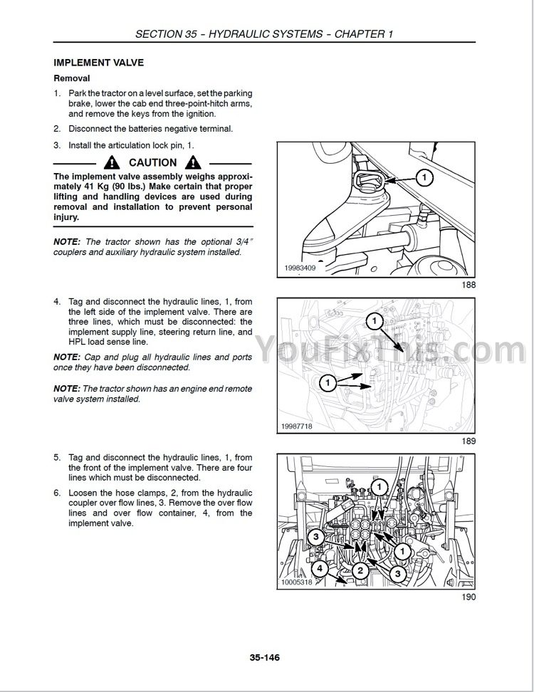
Implement Valve
Priority (Inlet) Valve Section
Tan (Float) Valve Section
Blue (Detent) Valve Section
Green (Standard) Valve Section
Implement Valve
1/2″ Couplers
Implement Valve Control Linkage
Control Lever Cable
Control Pedal Assembly
Control Pedal Cable
Steering Control Valve
In-Cab Flow Control Cables
Hydraulic System Hoses
3/4″ Couplers
Hydraulic Oil Heater
Engine End Remote Valves
Hydraulic Oil Cooler
Hydraulic Oil Cooler By-pass
Repair Time Schedule
Chapter – Cab-End Hitch
Specifications
Special Tools
Description of Operation
Three-Point Hitch Electrical Control Components
Three-Point Hitch Electrical Control System
Neutral – Manual Mode
Raise – Manual Mode
Lower – Manual Mode
Raise – Manual Mode – Fender Switches
Lower – Manual Mode – Fender Switches
Neutral – Automatic Mode
Raise – Automatic Mode
Lower – Automatic Mode
Raise – Automatic Mode – Fender Switches
Lower – Automatic Mode – Fender Switches
Float – Automatic Mode
Float Position Control – Automatic Mode
Hydraulic Lift Assembly Control Valve
Troubleshooting
Three-Point Hitch Controller Fault Codes
Electrical
Hydraulics
Adjustments
Calibration Mode
Upper Limit Operating Set Point Adjustment
Removal and Repair of Components
Raise/Lower Switches
Automatic,’Manual Switch
Status Light
Depth Control Potentiometer
Lowering Rate Potentiometer
External Three-Point Hitch Controls
Feedback Potentiometer
Hydraulic Lift Cover
Lift Cylinder
Cross Shaft
Control Valve
Upper Lift Link
Lower Lift Link Stabilizer Assembly
Lower Lift Link
Lift Assist Ram
Flexible Link Ends
Link Assembly
Repair Time Schedule
Chapter – Engine-End Hitch
Description of Operation
Three-Point Hitch Electrical Control Components
Three-Point Hitch Electrical Control System
Manual Mode
Automatic Mode
Hydraulic Lift Assembly Control Vah/e
Special Tools
Specifications
Troubleshooting
Electrical
Hydraulics
Adjustments
Calibration Mode
Upper Limit Operating Set Point Adjustment
Removal and Repair of Components
Status Light
Depth Control Potentiometer
Lowering Rate Potentiometer
Feedback Potentiometer
Cross Shaft
Control Valve
Center Lift Link
Stabilizer Assembly
Lower Lift Link
Hydraulic Cylinders
Flexible Link Ends
Lift Link Assembly
Repair Time Schedule
WHEELS, TIRES AND BALASTING
Chapter – Wheels and Tires
Introduction
Proper Jacking
Tire Inflation
Tire and Wheel Options
Chapter – Ballasting
Ballasting and Tires
Wheel Slippage
Ballast Limitations
Ballasting Recommendations
Cast Iron Weights
Liquid Ballast Calculations
FRAMES
Chapter – Frames
Specifications
Torques
Special Tools
Description of Operation
Introduction
Troubleshooting
Overhaul
Engine Hood
Hood Support Assembly
Side Panels, Right-hand and Left-hand
Front Grille
Cab-end Fenders
Left-hand and Right-hand
Engine-end Fenders
Left-hand and Right-hand
Heatshield
Engine End Drawbar
Cab End Drawbar
Front Axle Support
Frame Side Rails
Steering Pins
Pivot Pins
Front Frame
Rear Frame
Repair Time Schedule
CLIMATE CONTROL
Chapter – Climate Control
Specifications
Special Tools
Description and Operation
R134a Refrigerant Information
The Basics of Refrigeration
Individual Component Operation
Compressor and Clutch
Condenser
Receiver-drier
Thermal Expansion Valve
Evaporator/Heater Assembly
Blower Motor Assembly
Thermostatic Switch
High and Low Pressure Switches
Heater Control Valve
Switched Power: Fuses and HVAC Relay
Air Filtration
Troubleshooting and Testing
General Safety and Service Precautions
Recovering R134a Refrigerant With OEM1598
System Evacuation and Recharging With OEM1598
Oil Level Check Or Adjustment
Leak Detection
Performance Testing
Pressure, Temperature Relationship Chart
Conditions For Performance Testing
Gauge Readings and Interpretations
Performance Test and Diagnosis Summary
General Troubleshooting Summary
Heating System
Air Conditioning System
Air-conditioning Component Removal and Installation
Thermal Expansion Valve
Evaporator/Heater Assembly
Condenser
High and Low Pressure Switches
Compressor
Compressor Clutch
Receiver-drier
Air Conditioning Hoses
Heater Control Valve
Recirculation Door Control
Blower Speed Control
Heater Hoses
Repair Time Schedule
ELECTRICAL SYSTEM
Chapter – Electrical System
Specifications
Fuse and Relay Panel
Torque Specifications
Special Tools
Introduction
Electrical System
Using Schematics
Circuit Troubleshooting
Temporary Wiring Harness Repair
Description of Operation
Batteries
Starting and Charging Systems
Starter
Batteries Troubleshooting
Starter Troubleshooting
EICS Error Codes
EICS Connector Chart
Alarms
Three-Point Hitch Controller
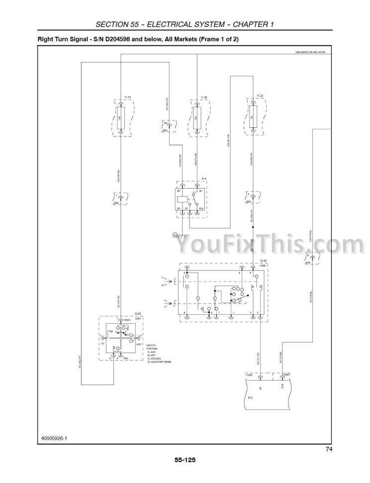
Chapter – Electrical Wiring Diagrams
Electrical Wiring Diagrams
Schematic Index
Disassembly and Repair
Alternator
Fan Belt Tensioner
Starter
Electronic Instrument Contol System (EICS)
Connectors
Repairing Connectors
Lamp Replacement
Harness Removal and Installation
Italian Brake Harness
Repair Time Schedule
ACCESSORIES
Introduction
Electrical Kits and Accessories
Frame and Platform
Hydraulic and PTO Kits
Loader Kits and Accessories
CAB
Specifications
Torque Specifications
Special Tools
Description of Operation
Troubleshooting
Removal and Installation
Cab Mounts
Cab
Cab Roof
Taillight Panel
Cab Fenders
Wiper Motor Cover
Windshield Wipers
Doors
Cab Door Lock and Latch
Lock Cylinder
Window Latch
Door Glass
Side Windows
Floor Mats
Seat Console
Fender Well Covers
Seat
Console Assembly
Steering Logic Valve Trip Linkage
Rotating Grommet Assembly
Headliner
Louvers
Radio and Speakers
Calibration (Adjustments)
Repair Time Schedule
Searches: 86615156, 86562957