


Part of the New Holland Repair Manuals.
New Holland built the 474, 489, 492, and 1465 Mower-Conditioners as one machine family, and OEM manual #86630605 documents all 170 pages of it, from PTO teardown to reel assembly rebuild. The exploded-view diagrams map every frame, cutter bar, wobble drive, and conditioning roll, alongside the Model 1465 light harness wiring and torque tables for ORFS fittings, pipe threads, and hydraulic tube connections. Step-by-step procedures cover knife replacement, slip clutch adjustment, main gearbox service, and reel bearing swaps. Need a number fast? Conditioner roll gap runs 0.38 mm to 2.5 mm lug-to-lug; the reel drive chain tensions to 6.3 mm deflection. When the machine is down, guessing burns hours. Open this bookmarked PDF on any device and search the spec by keyword.
What's Inside This New Holland 474, 489, 492, 1465 Repair Manual
| System | Pages | Key Topics |
|---|---|---|
| General Information | 3-20 | Foreword, Precautionary Statements, Safety, Serial Number, How the Mower-Conditioner Functions, Power Distribution, Tapered Spline Connections - Hammer Seating |
| Implement Power Take-Off (PTO) | 21-38 | Chapter 1 - PTO (PTO Assembly, Joint Replacement, Telescoping Shaft and Tube, Front PTO Assembly, PTO Shaft Shields, Quick-Detachable Yoke, PTO Drive Shaft, Repair Time Schedule) |
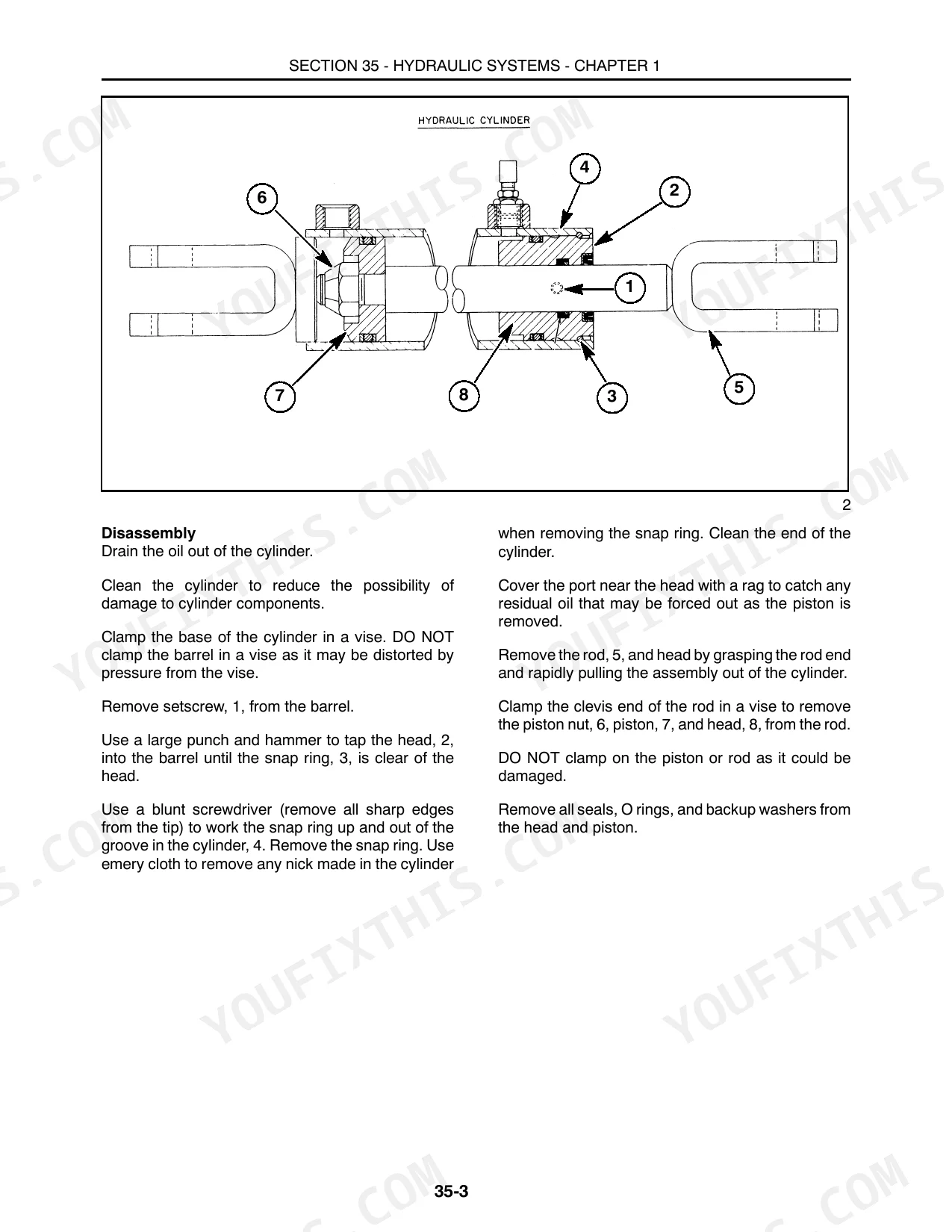
| Hydraulic Systems | 39-44 | Chapter 1 - Hydraulic Cylinders (Hydraulic Cylinders, Optional, Repair Time Schedule), Hydraulic Cylinders, Optional (Removing, Disassembly, Inspection, Assembly) |
| Frames | 45-70 | Lift Frame, Roll Frame, Header Frame, Repair Time Schedule |
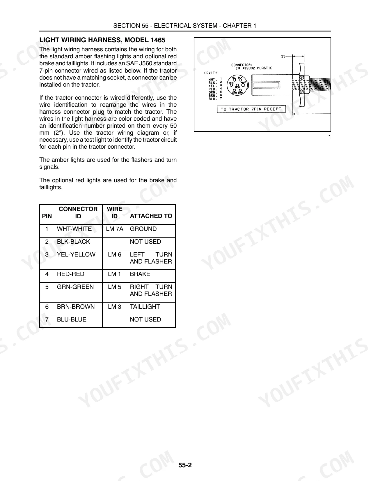
| Electrical System | 71-76 | Light Wiring Harness, Model 1465, Installing the Socket, Repair Time Schedule |
| Replacing the Knife Sections | 78-84 | Knife Assembly, Cutter Bar, Knife Head Bolt, Sharpening the Knife Sections |
| Repair Time Schedule | 85-93 | Guards, Knife Head, Knife Head Bushing, Hold-Down Clips |
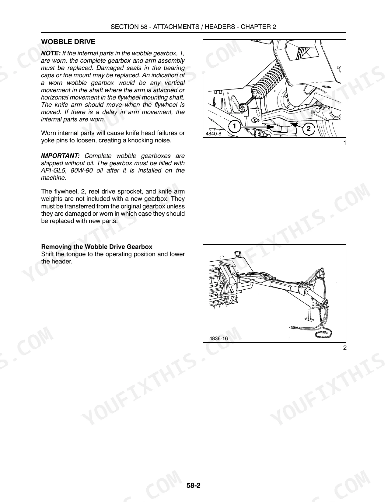
| Wobble Drive | 94-101 | - |
| Main Gearbox | 102-124 | Repair Time Schedule, Replacing the Knife Arm, Header Drive PTO and Jackshaft, Header Drive Belt |
| Replacing the Rolls | 125-133 | Repair Time Schedule, Rolls |
| Installing the Rolls | 134-141 | - |
| Drive Sprocket | 142-153 | Roll Pressure System, Repair Time Schedule, Reel Drive Belt, Reel Drive Chain, Drive Sheaves, Reel Drive Sheave, Sprocket, And Jackshaft |
| Repair Time Schedule | 154-164 | Reel Shaft Bearings, Cam Follower Bearing, Reel Tine Bar Clearance with Cam Track, Replacing the Bearings, Replacing the Tines, Reel Shaft End Play, Installing the Reel Assembly and Cam Track, Removing the Reel Assembly and Cam Track |
| Safety Decals | 165-170 | - |
Quick Reference Specifications
| Specification | Value | Page |
|---|---|---|
| Models 474, 489, and 492 | ||
| Reel drive chain deflection | 6.3 mm (1/4″) | p. 150 |
| Reel drive chain deflection (adjusted by idler) | 6.3 mm (1/4″) | p. 150 |
| All Models | ||
| Reel drive chain R&R time | 0.50 hours | p. 163 |
| Minimum roll gap between lugs | 0.38 mm (0.015″) | p. 128 |
| Maximum roll gap | 2.5 mm (0.100″) | p. 128 |
| Reel drive sprocket R&R time | 1.00 hours | p. 163 |
| Maximum reel shaft end play | 0.75 mm (0.030″) | p. 157 |
| Cam follower bearing R&R time | 0.25 hours | p. 163 |
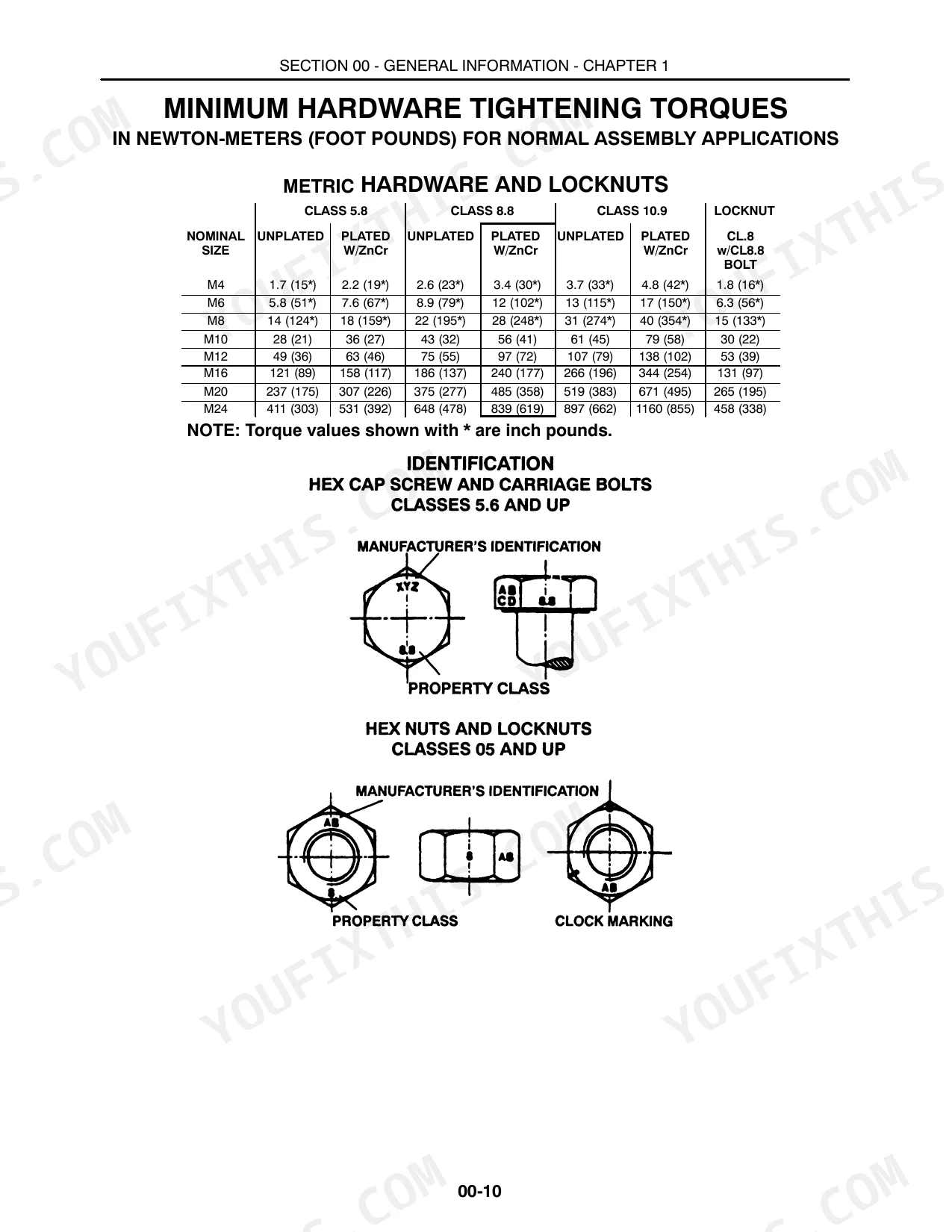
| Metric Hardware Torque (M4, Class 5.8, Unplated) | 1.7 N·m | p. 12 |
| Inch Hardware Torque (1/4", SAE Grade 2, Unplated) | 6.2 N·m | p. 13 |
| Hydraulic Tube Nut Torque (1/4" OD, 7/16-20 thread) | 12-16 N·m | p. 14 |
| Model 1465 | ||
| Spring-loaded idler spring bolt extension | 22 mm (7/8″) | p. 150 |
New Holland 474, 489, 492, 1465 Common Problems This Manual Covers
Sudden plugging every few feet while cutting hay on the 489
Inspect the reel drive chain and its sprockets. Adjust the tension idler until chain deflection measures exactly 6.3 mm (1/4"), the figure given on page 150. If stretch on the #40 roller chain (shared by the 474, 489, and 492) prevents proper tensioning or causes binding, replace it.
Manual Section: Section 58 -- Attachments / Headers p. 150Hay feed becomes highly inconsistent and heavy crop bunches up at the conditioner rollers
Measure the clearance between the upper and lower conditioning rolls. Confirm the minimum lug-to-lug gap is at least 0.38 mm (0.015"), per page 128. If the rubber is badly split or missing, replace the entire roll assembly.
Manual Section: Section 58 -- Attachments / Headers p. 128Excessive vibration and frequent reel drive drivetrain breakdowns during heavy field operation
Check the reel shaft bearings for severe wear or looseness. Adjust the bearing flanges so reel shaft end play stays within 0.75 mm (0.030"), as page 157 specifies. If end play remains out of spec, replace the bearings and mounting hardware.
Manual Section: Section 58 -- Attachments / Headers p. 157Cutter bar knife assembly knocks loudly and cuts crop poorly in thick field conditions
Examine the wobble drive gearbox and knife head connections for loose hardware. Torque the knife head bolts to 190 N·m, the value specified on page 78. Confirm the wobble gearbox flywheel cap screws are tight, then sharpen or replace any dull knife sections.
Manual Section: Section 58 -- Attachments / Headers p. 78Frequently Asked Questions
How do I reset or adjust the hydraulic lift on a New Holland haybine?
The hydraulic lift is set through the header flotation springs: adjust them so it takes no more than 310 N (70 lbs.) to just start lifting the header. You'll find the steps in the 'Installation' subsection for the Lift Frame. p. 65
What are the torque specs for haybine gearbox or wobble box bolts?
For the wobble gearbox, the cap screw attaching the flywheel to the input shaft should be torqued to 108 N∙m (80 ft. lbs.). The four cap screws attaching the gearbox to the frame should be torqued to 258 N∙m (190 ft. lbs.). Additionally, the nut for the knife arm should be tightened to 271 - 285 N∙m (200 - 210 ft. lbs.). p. 98
What are the torque specs for New Holland 489/492 roller or knife head fasteners?
The knife head bolt should be torqued to 190 N∙m (140 ft. lbs.) with the knife in the center of its stroke. Locknuts for knife sections should be torqued to a maximum of 8 - 11 N∙m (70 - 100 in. lbs.). For Models 474, 489, and 492, the upper roll drive shaft cap screw should be tightened to 108 N∙m (80 ft. lbs.). p. 78
What do I get after purchasing this New Holland 474, 489, 492, 1465 manual?
Checkout delivers a 170-page searchable PDF that downloads instantly. Open it on a laptop, tablet, or phone and take it straight to the shop floor.
Am I able to print pages from this manual?
No restrictions at all. Print individual pages, full chapters, or the entire manual. The PDF is completely unlocked.
Does this manual have electrical diagrams?
Yes. You'll find full electrical schematics with wire routing diagrams, connector identification, and circuit descriptions.