
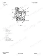
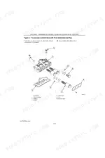
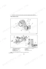
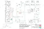
This is the full factory repair manual for the New Holland TG210, TG230, TG255 and TG285 row-crop tractors - 3346 pages covering the 8.3 litre 24 valve CDC 6TAA Magna Force engine, the 18 forward speed full powershift transmission, MFD and Supersteer front axles, the CCLS piston pump hydraulic system, and every electronic controller on the machine. These tractors live and die by their controllers, and this manual prints the actual fault code lists: engine ECM codes from page 615, TRANS codes from page 2826, plus hitch, armrest, remote hydraulics, PTO and instrument cluster chapters in Section 55. Both electrical eras are bound in - full sheet schematics before and after P.I.N. JAW129992 - so you get the right wiring diagram for your serial number.
Complete the set for your TG210, TG230, TG255…
- Parts Catalog: New Holland TG210–TG285 Series Parts Catalog
- Parts Catalog: New Holland TG210–TG285 Series Parts Catalog
- Parts Catalog: New Holland TG285 Tractor Parts Catalog
What's Inside This New Holland TG210, TG230, TG255, TG285 Repair Manual
| System | Pages | Key Topics |
|---|---|---|
| General Information, Safety and Standard Torques | 1-31 | Standard Torque Specifications, Safety, Maintenance Schedule, General Specifications, Special Torques |
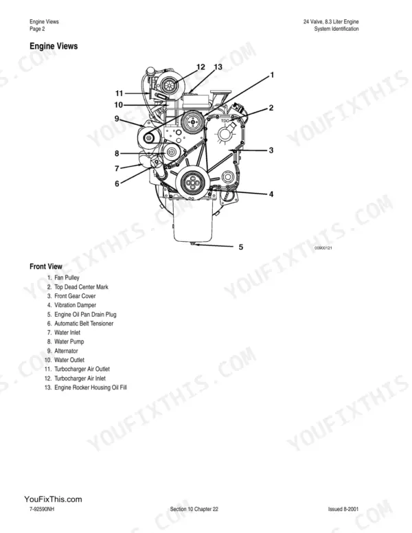
| Engine - 8.3 Litre 24 Valve | 32-1130 | Engine Removal and Installation, Fuel Tank Removal, Radiator and Coolers, Engine Overhaul, Engine Fault Codes, Service Tools |
| Power Take-Off | 1131-1257 | PTO Assembly, PTO Clutch Assembly, Power Take Off Control System |
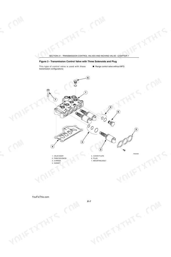
| Transmission, Rear Frame and Hydraulic Pump Drive | 1258-1573 | Powershift Transmission System, Speed Transmission, Range Transmission, Transmission Control Valves, Inching Valve, Rear Frame, Tractor Splits |
| Front System and MFD Axles | 1574-1785 | MFD Control System, MFD Clutch, MFD Driveshaft, Suspended MFD Axle, Supersteer Axle, Locking MFD Differential, Planetary Hub |
| Rear Axle and Planetaries | 1786-1817 | Rear Axle Overhaul, Planetary Hubs |
| Brakes | 1818-1867 | Brake Valve, Brake Cylinders, Park Brake, Trailer Brake Systems |
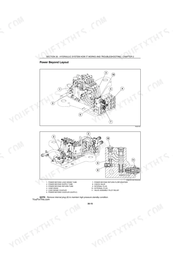
| Hydraulic System and Hitch | 1868-2053 | Hydraulic Schematic Symbols, System Operation and Troubleshooting, Remote Valve and Coupler Service, Priority and Regulator Valve, Charge Pump, Closed Centre Load Sensing Piston Pump, Hitch System, Hitch Control Valve |
| Steering | 2054-2065 | Steering Column, Steering Hand Pump |
| Air Conditioning | 2066-2287 | A/C Troubleshooting, System Service, Pressure Switch Values |
| Electrical System | 2288-3311 | Electrical Operation and Troubleshooting for Both P.I.N. Eras, Instrumentation Programming and Fault Codes, Hitch Controller Calibration, Transmission Controller Calibration, Armrest Controller, Remote Hydraulics Controller, PTO Controller, Performance Monitor, Instrument Cluster ICU2 |
| Pedals and Cab | 3312-3335 | Pedal and Pedal Switch Adjustment, Cab Raise, Cab Removal and Installation |
| Electrical Schematics | 3336-3343 | Full Sheet Schematic Prior to P.I.N. JAW129992, Full Sheet Schematic P.I.N. JAW129992 and After, Fuse Relay and Connector Tables |
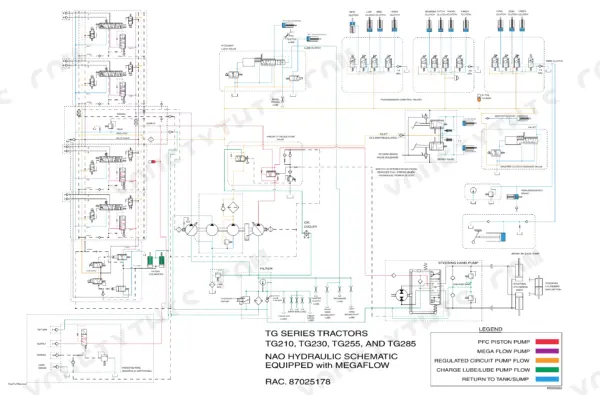
| Hydraulic Schematic and Air Conditioning Chart | 3344-3346 | Full Sheet Hydraulic Schematic with Megaflow, Air Conditioning Troubleshooting Chart |
Quick Reference Specifications
| Specification | Value | Page |
|---|---|---|
| Engine | CDC 6TAA Magna Force, 8.3 litre, 24 valve | p. 28 |
| Engine bore and stroke | 114 mm x 135 mm | p. 28 |
| Firing order | 1-5-3-6-2-4 | p. 28 |
| Rated engine speed | 2200 RPM | p. 28 |
| Valve clearance, engine cold | Intake 0.25 mm (0.010 in), exhaust 0.50 mm (0.020 in) | p. 28 |
| Cylinder head capscrew torque, 14 mm | Step 1: 148 N·m (108 ft-lb); Step 2: recheck all at 148 N·m | p. 286 |
| Transmission | 18 forward / 4 reverse, full powershift | p. 28 |
| Creeper option | 6 forward / 2 reverse | p. 28 |
| Hydraulic pump | Axial piston, closed centre load sensing | p. 24 |
| Hydraulic maximum pressure at pump | 224 bar (3250 psi) | p. 24 |
| Hydraulic low pressure standby | 340 to 390 psi (23.5 to 27 bar) | p. 1919 |
| Remote coupler flow at 2000 RPM | Standard 136 l/min (36 gpm); Mega Flow 244 l/min (64 gpm) | p. 24 |
| Hitch | Three point Category III, electronic position and draft control | p. 28 |
| Hitch lift capacity at 610 mm behind lift point | 6134 to 7301 kg (13 520 to 15 970 lb) by model | p. 28 |
| Engine oil capacity, with filter change | 21 litres (5.5 US gal) | p. 24 |
| Coolant capacity | TG210/TG230 22.7 litres (6 US gal); TG255/TG285 24.6 litres (6.5 US gal) | p. 24 |
| Transmission and hydraulic capacity | 172 litres (45.5 US gal) | p. 24 |
| Fuel tank capacity | TG210/TG230 492 litres (130 US gal); TG255/TG285 606 litres (160 US gal) | p. 24 |
| Electrical system | 12 volt negative ground, two 1000 CCA group 31 batteries, Bosch 135 amp alternator | p. 24 |
| Air conditioning | HFC-134A, 2100 g (4.63 lb) charge, Sanden SD7H15 compressor | p. 28 |
New Holland TG210, TG230, TG255, TG285 Common Problems This Manual Covers
Powershift hesitates, jerks or loses drive under load
Run the transmission controller calibration in Section 55 Chapter 4 before opening anything up. TRANS 125 through 127 mean uncalibrated clutches, and TRANS 147 flags regulated pressure below 290 PSI, which points you at the regulated circuit instead of the clutch packs.
Manual Section: Section 55 Chapter 4, Transmission Controller Calibration and Fault Codes, from page 2826 p. 2826Three point hitch lifts slowly, hunts, or will not lift at all
Section 55 Chapter 3 covers hitch controller calibration and its fault codes - do the calibration first, since a swapped controller or dropped calibration causes most erratic hitch behaviour. If codes are clean, the hitch control valve service is in the Section 35 hydraulic and hitch chapters.
Manual Section: Section 55 Chapter 3, Hitch Controller, from page 2746 p. 2746Weak hydraulics - sluggish remotes, poor loader response
Test CCLS pump low pressure standby against the 340 to 390 psi spec on page 1919, then follow the Section 35 troubleshooting flow from page 1868 through the priority and regulator valve and charge pump. The bound-in NAO hydraulic schematic with Megaflow lets you trace the circuit line by line.
Manual Section: Section 35, Hydraulic System Operation and Troubleshooting, from page 1868 p. 1868Air conditioning stops cooling or cycles constantly
Section 50 gives the A/C troubleshooting chart and system service for the Sanden SD7H15 system with its 2100 gram HFC-134A charge. Check the high pressure switch against the printed values - it opens above 400 psi plus or minus 10 and closes below 250 psi plus or minus 10 (page 2089).
Manual Section: Section 50, Air Conditioning Troubleshooting and Service, from page 2066 p. 2066Frequently Asked Questions
My TG is throwing transmission codes and jerking between shifts. Does this manual decode them?
Yes. Section 55 Chapter 4, starting at page 2826, lists the TRANS codes in the form the display shows them. For example TRANS 147 means regulated system pressure below 290 PSI, and TRANS 125 through 127 mean a clutch is not calibrated. The same chapter walks you through the transmission controller calibration procedure, which fixes most of the harsh shifting complaints on these tractors without any parts. p. 2826
Are the engine ECM fault codes included, and how do I find the ECM?
Section 10 Chapter 24, from page 615, covers the engine ECM fault codes for the 8.3 litre 24 valve engine. Each code entry gives the SPN:FMI pair and the lamp colour - for example Fault Code 111 is an ECM internal hardware error, SPN:FMI 12, yellow lamp. The manual also tells you the ECM sits on the left side of the engine block behind the fuel filter, which saves you crawling around looking for it. p. 619
Does it have the wiring schematic for my serial number range?
Both. The electrical system changed at P.I.N. JAW129992, and this manual binds in the full sheet schematic for tractors before that number and a separate full sheet schematic for JAW129992 and after, plus fuse, relay and connector tables. The Section 55 troubleshooting chapters cover both P.I.N. eras, so you are not guessing which diagram matches the harness in front of you. p. 3340
I need torque specs for a head job on the 8.3. Are they in here?
Yes. The engine overhaul chapters carry the specs - the 14 mm cylinder head capscrews torque to 148 N.m (108 ft-lb) in step 1, then you recheck all of them at 148 N.m in step 2 (page 286). Cold valve clearance is 0.25 mm intake and 0.50 mm exhaust, firing order 1-5-3-6-2-4, bore and stroke 114 x 135 mm. Standard torque charts for everything else are up front in Section 00. p. 286
My remotes and hitch are slow. What pressure numbers should I be testing against?
Start with the CCLS piston pump low pressure standby test on page 1919 - spec is 340 to 390 psi (23.5 to 27 bar). Maximum system pressure at rated RPM is 224 bar (3250 psi) at the pump. If standby checks out, Section 35 hydraulic troubleshooting from page 1868 works through the priority and regulator valve, charge pump and remote couplers. Standard remotes should flow 136 l/min at 2000 RPM, Mega Flow 244 l/min. p. 1919

Reviews
There are no reviews yet.