
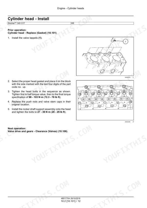
Factory service manual for the New Holland Boomer 54D CVT compact tractor with the R 753 IE4 diesel - 2.228 l (135.96 in3), 39.5 kW (53.0 Hp) gross. It covers full teardown and rebuild: engine, the CVT and its control system, 4WD, front and rear axles, PTO, brakes, hydraulics, steering, cab climate control, and bodywork. The electrical section includes wiring schematics. Real numbers throughout: cylinder head bolts at 98-103 N.m (72.3-76 lb ft), steering relief at 14479 kPa (2100 psi), rear wheel disc-to-rim at 244 N.m (180 lb ft). Both Cab and ROPS versions are covered, and this is a Tier 4B Final machine with proper electronic diagnostic procedures.
Complete the set for your Boomer 54D CVT
- Operator Manual: New Holland Boomer 54D Operator Manual
- Operator Manual: New Holland Boomer 46D CVT, 54D CVT Operator Manual
What's Inside This New Holland Boomer 54D CVT Manual
| System | Pages | Key Topics |
|---|---|---|
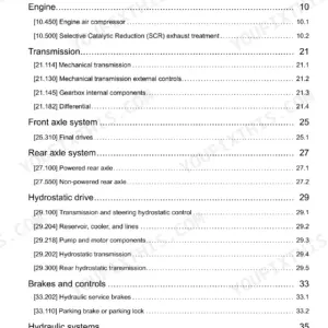
| Engine | 61-296 | Cylinder Heads, Crankshaft and Flywheel, Fuel Injection System, Turbocharger, Lubrication System, Cooling System |
| Transmission | 297-446 | Continuously Variable Transmission (CVT), Transmission Control System |
| Four-Wheel Drive (4WD) System | 447-462 | Mechanical Control, Powered Front Axle, Front Bevel Gear Set and Differential |
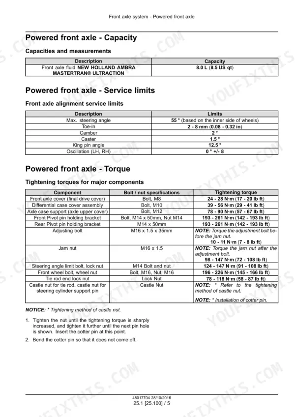
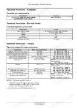
| Front Axle System | 463-578 | Powered Front Axle, Front Axle Housing and Differential, Hub Carriers and Final Drives, Steering Knuckles, Removal, Disassembly and Assembly, Bolt Tightening Specifications |
| Rear Axle System | 579-644 | Powered Rear Axle, Rear Bevel Gear Set and Differential, Final Drives |
| Power Take-Off (PTO) | 645-720 | Rear Electro-Hydraulic Control, One-Speed Rear PTO, Central PTO |
| Brakes and Controls | 721-758 | Parking Brake, Parking Lock, Mechanical Service Brakes |
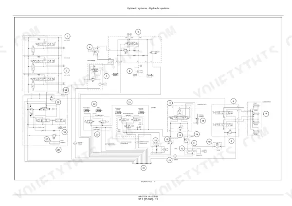
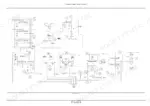
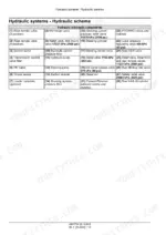
| Hydraulic Systems | 759-912 | Fixed Displacement Pump, Remote Control Valves, Reservoir, Cooler, And Filters |
| Steering | 913-972 | Hydraulic Control Components, Pump, Cylinders |
| Cab Climate Control | 973-1106 | Heating, Ventilation, Air Conditioning |
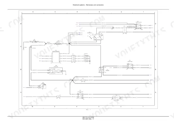
| Electrical System Overview and Troubleshooting | 1107-1266 | Electrical System Description, Component Location, Circuit Troubleshooting, Grounds and Power Supply, Transmission Control System |
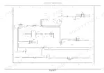
| Harnesses and Connectors | 1267-1577 | Electrical Schematic Sheets with Component Legends, Wire Identification by Color and Gauge, Connector Pinouts, Cross-Sheet References, Harness Routing |
| Engine Starting System and Battery | 1578-1621 | Starter Motor, Glow Plug Control Unit, Neutral Start and Crank Relays, Battery Service, Charging Circuit and Alternator |
| External Lighting | 1622-1633 | Head, Tail and Work Lights, Turn Signals and Hazard Circuit, Light Switch, Bulb Replacement |
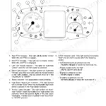
| Warning Indicators, Alarms, and Instruments | 1634-1655 | STOP Indicator Conditions, CVT Oil Pressure and Coolant Temperature Warnings, Instrument Cluster, Audible Alarms, Service Reminders |
| Wiper and Washer System | 1656-1663 | Wiper Motor, Washer Pump, Switch Circuit, Removal and Installation |
| Electronic Modules and EGR Electrical System | 1664-1713 | Transmission Control Unit, Engine Control Module, Module Replacement and Programming, Exhaust Gas Recirculation Electrical Circuit |
| Fault Codes | 1714-2106 | Fault Code List by Control Module, Context and Cause for Each Code, Possible Failure Modes, Connector and Pin References, Clearing Codes After Repair |
| Platform, Cab, Bodywork, and Decals | 2107-2193 | Engine Hood and Panels, Fenders and Guards, Operator Seat, Cab Interior |
Quick Reference Specifications
| Specification | Value | Page |
|---|---|---|
| All Models | ||
| Engine Gross Horsepower | 39.5 kW (53.0 Hp) | p. 45 |
| Engine Displacement | 2.228 l (135.96 in3) | p. 45 |
| Maximum Lift Capacity at Ball Ends | 1606 kg (3541 lb) | p. 44 |
| Weight (with Cab and Tires) | 2240 kg (4940 lb) | p. 49 |
| Weight (with ROPS and Tires) | 1900 kg (4190 lb) | p. 49 |
| Front Wheel Disc-to-Hub Torque | 129 N.m (95 lb ft) | p. 31 |
| Rear Wheel and Disc-to-Axle Torque | 129 N.m (95 lb ft) | p. 31 |
| Rear Wheel Disc-to-Rim Torque | 244 N.m (180 lb ft) | p. 31 |
| Hydraulic systems | ||
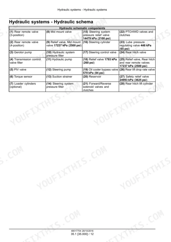
| Steering Circuit Relief Valve Pressure | 14479 kPa (2100 psi) | p. 773 |
| Mid Mount Valve and Rear Hitch Relief Pressure | 17237 kPa (2500 psi) | p. 773 |
| Cooler Bypass Valve Pressure | 579 kPa (84 psi) | p. 773 |
| Safety Relief Valve Pressure | 24993 kPa (3625 psi) | p. 773 |
| Lube Regulating Valve Pressure | 448 kPa (65 psi) | p. 773 |
| Engine | ||
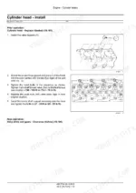
| Cylinder Head Bolts Final Torque | 98-103 N.m (72.3-76 lb ft) | p. 99 |
| Rocker Shaft Support Assembly Bolts Torque | 27-39 N.m (20-29 lb ft) | p. 99 |
| M12 x 40 Engine Mounting Bolts Torque | 115 N.m (85 lb ft) | p. 75 |
| Valve Cover Retaining Bolts Torque | 12-16 N.m (9-19 lb ft) | p. 92 |
| Compression Pressure | 2944 kPa (427 psi) plus or minus 345 kPa (50 psi) | p. 93 |
| Cooling System Capacity | 9 L (2 US gal) | p. 66 |
| Engine Crankcase Oil Capacity | 6.3 L (2 US gal) | p. 66 |
New Holland Boomer 54D CVT Common Problems This Manual Covers
Lift arms slowly leak down when the engine is shut off
The hydraulic troubleshooting charts pin this to three causes: a damaged lift cylinder piston seal, a mis-adjusted discharge valve, or a lift check/safety valve that is not seating. The section also includes a full-page hydraulic circuit schematic in ISO symbols so you can trace exactly where the oil is escaping.
Manual Section: Hydraulic systems (pages 759-912) p. 833Starter pinion engages the ring gear but the motor will not turn
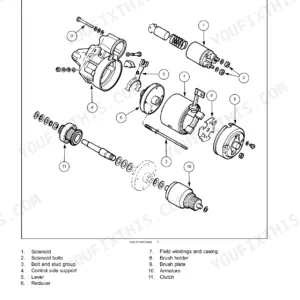
The starter troubleshooting procedure tells you to check for a broken or defective ground connection between the solenoid and battery, or a solenoid-to-motor lead wire that is not tightened properly. Cheap fixes, but only if you know to look there before condemning the starter itself.
Manual Section: Electrical systems - starting motor troubleshooting p. 1587Engine shuts down unexpectedly or will not stay running
The manual explains that the operator safety module controls the fuel shutoff solenoid relay - if current to the module is interrupted, the relay de-energizes and fuel to the solenoid is cut, stopping the engine. Knowing that chain lets you test the module circuit instead of blindly swapping fuel system parts.
Manual Section: Electrical systems - operator safety module p. 1134Hazard flashers dead or intermittent
The electrical troubleshooting procedure for the hazard flasher circuit walks you through inspecting the wiring harness and ground terminals for damage, corrosion, and short circuits, then repairing or replacing as needed. Pair that with the full schematics and wire color codes in the same section and you can trace the circuit end to end.
Manual Section: Electrical systems - wiring harness and lighting circuits p. 1234Frequently Asked Questions
Does the manual list fault codes for the Boomer 54D, and how do I read them?
Yes, and it is the largest single part of the book. Electrical systems - FAULT CODES runs from page 1714 to page 2106, listing codes by control module with, for each one, the context, the cause, and the possible failure modes down to the connector and pin. A typical entry reads "2433-Pulley 2 pressure sensor short to 5V or 12V", Control Module: TCU, and it walks you from the symptom to the specific circuit. To pull codes off the machine you enter diagnostic mode with jumper tool 380000843 on the diagnostic connector, then read the cluster. After the repair the manual tells you to clear the code and test the system operation. p. 1714
Are full wiring diagrams included, or just a summary schematic?
Yes. The Electrical systems section runs from page 1107 to 2107 - about half the book - with a Harnesses and connectors chapter and wiring schematics. That is what you actually need when you are chasing a corroded ground or a shorted harness instead of guessing at wire runs with a test light. p. 1272
The red STOP light comes on with the alarm. Does the manual explain what triggers it?
Yes. The manual lists four conditions that light the red STOP indicator with an alarm: a CVT oil pressure problem, high coolant temperature, low engine oil pressure, or low driveline oil pressure. From there the instrument cluster and diagnostic mode procedures let you narrow down which one you are dealing with before you start pulling panels. p. 1635
Is the CVT actually covered, or does the manual just say 'see dealer'?
The Continuously Variable Transmission and its control system get their own service coverage in the transmission section. Since CVT oil pressure is one of the faults serious enough to trip the red STOP light, having the transmission control system procedures in hand matters on this machine. This is not a manual that punts the hard part to the dealership. p. 297
Does it include real torque specs, or just exploded parts views?
Real specs, with values in both metric and imperial. Examples from the book: cylinder head bolts final torque 98-103 N.m (72.3-76 lb ft), rocker shaft support bolts 27-39 N.m (20-29 lb ft), front wheel disc-to-hub 129 N.m (95 lb ft), rear wheel disc-to-rim 244 N.m (180 lb ft). The front axle section even has its own bolt tightening specification tables. Compression spec is in there too: 2944 kPa (427 psi) plus or minus 345 kPa (50 psi). p. 99
Reviews
There are no reviews yet.