
![New Holland TC5.80 service manual - Electrical Systems: Circuits, Harnesses and Connectors, X-602 - WIPER SWITCH [ S-002] (84159859) (Female)](https://youfixthis.com/wp-content/uploads/2026/07/new-holland-tc5-80-tc5-90-hillside-service-manual-page-1009-600x848.webp "new-holland-tc5-80-tc5-90-hillside-service-manual-page-1009.webp")
![New Holland TC5.80 service manual - Electrical Systems: Circuits, Harnesses and Connectors, X-602 - WIPER SWITCH [ S-002] (84159859) (Female)](https://youfixthis.com/wp-content/uploads/2026/07/new-holland-tc5-80-tc5-90-hillside-service-manual-page-1009-150x212.webp "new-holland-tc5-80-tc5-90-hillside-service-manual-page-1009.webp")
Part of the New Holland Repair Manuals.
This is the factory service manual for the New Holland TC5.80, TC5.90 and TC5.90 Hillside combines, Tier 4B, part number 48001074. It works through the machine the way New Holland builds it, then follows the crop path from header attachment through feeding, threshing, separation, residue handling, cleaning and unloading. Read one thing before you diagnose the hydraulics: the machine carries two pumps without lateral flotation and three with it, so the circuit in front of you depends on how your combine was specified.
What's Inside This New Holland TC5.80, TC5.90, TC5.90 Hillside Manual
| System | Pages | Key Topics |
|---|---|---|
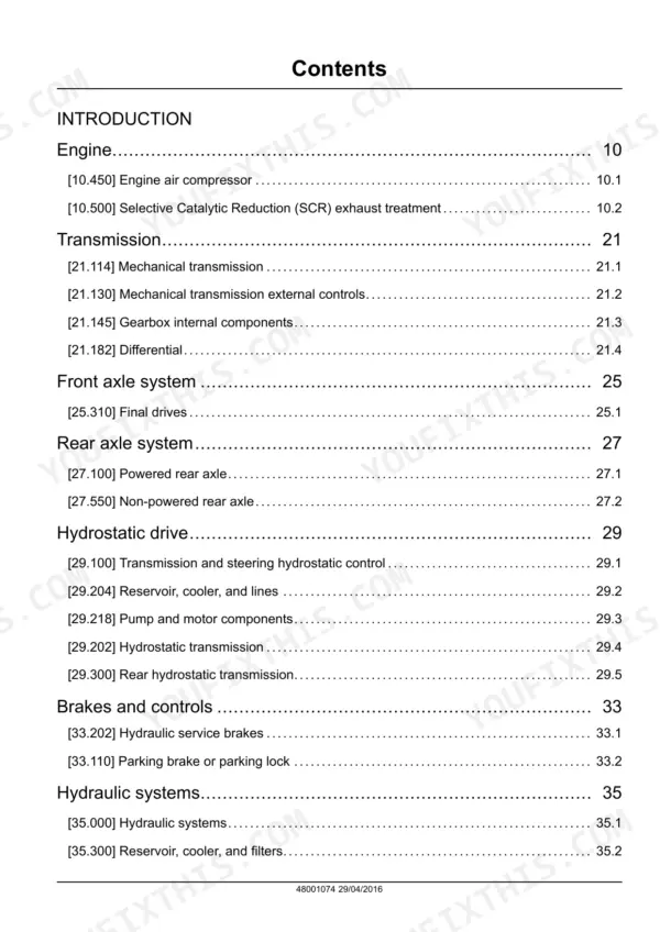
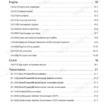
| Introduction and Standard Torques | 9-44 | How to Use the Manual, Shop Safety, Standard Tightening Torques, Approved Fluids and Consumables |
| Engine | 45-78 | Engine Installation and Mountings, Cooling Package, Air Intake and Exhaust with Selective Catalytic Reduction, Fuel Supply, Engine Ancillaries |
| Transmission | 79-184 | Gearbox and Range Unit, Drive Shafts and Final Drives, Transmission Controls and Overhaul |
| Front Axle System | 185-222 | Front Drive Axle and Final Drives, Hubs and Bearings, Axle Rebuild |
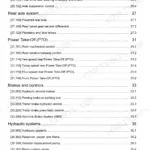
| Rear Axle System | 223-254 | Steering Rear Axle, Hubs, King Pins and Bearings |
| Hydrostatic Drive | 255-330 | Hydrostatic Pump and Drive Motors, Charge Circuit, Ground Drive Control, Drive Pressure Testing and Pump Overhaul |
| Brakes and Controls | 331-374 | Service Brakes, Parking Brake, Brake Circuit and Bleeding |
| Hydraulic Systems | 375-482 | Two or Three Pumps Depending on Lateral Flotation, Main, Steering and Lateral Flotation Gear Pumps with Their Pressures and Flows, Load Sensing and Proportional Pwm Valves, Header Suspension and Lateral Float Accumulators, Unloading Tube Valve, Pressure Testing |
| Steering | 483-514 | Steering Circuit and Cylinder, Steering Pump Supply, Steering Column, Fault Finding |
| Cab Climate Control | 515-566 | Heating, Ventilation and Air Conditioning, Compressor and Condenser, Refrigerant Handling, Charging and Leak Testing |
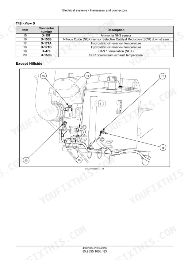
| Electrical Systems: Circuits, Harnesses and Connectors | 567-1239 | Electrical System Architecture, Complete Wire Harness Drawings, Connector Component Diagrams, Fuse and Relay Layouts, Pin-Out Tables |
| Electrical Systems: Emissions, Climate and Machine Controls | 1240-1294 | Selective Catalytic Reduction Control, Heating Ventilation and Air-Conditioning Circuits, Sieve Electric Control, Reverser Electric Control |
| Electrical Systems: Machine Fault Codes and Diagnostics | 1295-2050 | Machine-Side Fault Codes in the E0xxx Family, From Straw Walker Loss Sensor Voltage Faults to Sieve and Reverser Control Faults, Each with Its Guided Diagnostic and the Harness Checks It Calls for |
| Electrical Systems: Engine and Aftertreatment Fault Codes | 2051-2626 | Engine and Emissions Fault Codes in the E17xxx, E19xxx and E3xxx Families with Their Dtc References, Including DEF/AdBlue Supply Module, Exhaust Flap CAN Timeout, Injector Short Circuit and Prefilter Fuel Pressure Sensor Faults |
| Attachments and Headers | 2627-2648 | Header Attachment and Drive, Header Suspension, Multi-Coupler, Header Service |
| Product Feeding | 2649-2720 | Feeder House and Elevator, Stone Trap, Feed Beater and Drive, Reversing Drive |
| Threshing | 2721-2768 | Threshing Cylinder and Concave, Concave Clearance and Cylinder Speed, Threshing Drive |
| Separation | 2769-2798 | Straw Walkers and Separation Grate, Separation Drive and Bearings |
| Residue Handling | 2799-2818 | Straw Chopper and Spreader, Chaff Spreader, Residue Drive |
| Cleaning | 2819-2934 | Cleaning Shoe, Sieves and Chaffer with Their Electric Control, Cleaning Fan and Drive, Returns System, Hillside Self-Levelling Arrangement |
| Crop Storage and Unloading | 2935-2986 | Grain Tank and Level Sensors, Unloading Tube Valve and Auger, Unloading Control |
| Platform, Cab, Bodywork and Decals | 2987-3019 | Cab and Platform Assembly, Bodywork Panels, Glazing, Decals, Component Removal |
| Special Tool Index | 3020-3023 | Part Numbers of the Special Service Tools Each Procedure Calls for |
Quick Reference Specifications
| Specification | Value | Page |
|---|---|---|
| Models without / with lateral flotation | ||
| Number of hydraulic pumps | Two / three | |
| Main hydraulic pump | ||
| Type and rotation | Silence gear type, right-hand rotation | |
| Displacement and maximum flow, Main hydraulic pump | 16 cc/rev; 48 l/min (10.5 gal/min) at 3000 rpm maximum speed | |
| Main and steering pumps | ||
| Maximum pressure (Main and steering pumps) | 280 bar (4061 psi) | |
| Steering circuit pump | ||
| Displacement and maximum flow, Steering circuit pump | 5.5 cc/rev; 16.5 l/min (3.6 gal/min) | |
| Third pump circuit | ||
| Maximum pressure, Third pump circuit | 230 bar (3336 psi) | |
| Lateral float accumulator | ||
| Charge pressure, Lateral float accumulator | 120 bar (1740.0 psi) | |
| Lateral float accumulator, second unit | ||
| Charge pressure (Lateral float accumulator, second unit) | 85 bar (1232.5 psi) | |
| Hydraulic return circuit | ||
| Return pressure | Up to 1.15 bar (17 psi) | |
| All models | ||
| Emissions aftertreatment | Tier 4B with Selective Catalytic Reduction | |
New Holland TC5.80, TC5.90, TC5.90 Hillside Common Problems This Manual Covers
Hydraulic pressures do not match the figures you expect.
Confirm the pump count before you conclude anything. A combine without lateral flotation has two pumps and one with it has three, and the third circuit is limited to 230 bar rather than the 280 bar of the main and steering pumps. Measure the main pump against 48 l/min at up to 3000 rpm and the steering pump against 16.5 l/min, and remember that return oil runs at up to 1.15 bar, which is normal rather than a leak.
Manual Section: Hydraulic SystemsOn a Hillside machine the levelling is slow, drifts, or feels spongy.
Check the accumulator charges first. The lateral float circuit uses one accumulator at 120 bar and one at 85 bar, and a soft accumulator produces exactly that behaviour long before the pump or the cylinders are at fault. The hydraulic section names the accumulator control valve and the header suspension accumulator on the same circuit, so check the whole group rather than one unit.
Manual Section: Hydraulic SystemsThe machine derates or logs a fault code with no visible mechanical cause.
Read the code and go to the fault-code section, which is split between machine codes (from page 1295) and engine and aftertreatment codes (from page 2051) and carries the DTC reference and the guided diagnostic for each one. Codes from the Selective Catalytic Reduction system look like engine faults from the seat but are diagnosed through their own electrical chapter, and sensor faults such as intake air humidity have their own procedures. Follow the harness drawing to the connector the test names.
Manual Section: Electrical Systems: Engine and Aftertreatment Fault CodesFrequently Asked Questions
Which combines does this manual cover?
The TC5.80, the TC5.90 and the TC5.90 Hillside, all Tier 4B, under part number 48001074. The crop path, the drives and the electrical architecture are shared; the Hillside adds its self-levelling arrangement, which the cleaning section covers.
How many hydraulic pumps does my combine have?
Two if it was built without lateral flotation, three if it was built with it. That is stated in the pump specification and it matters before you measure anything. The main pump is a silence gear type of 16 cc per revolution giving 48 l/min (10.5 gal/min) at up to 3000 rpm, the steering pump is 5.5 cc per revolution giving 16.5 l/min (3.6 gal/min), and both are limited to 280 bar (4061 psi). The third pump, where fitted, feeds the lateral flotation circuit.
What accumulator pressures does it specify?
Two lateral float accumulators, one charged to 120 bar (1740.0 psi) and one to 85 bar (1232.5 psi). The hydraulic section also names the header suspension accumulator and the accumulator control valve, and it notes that return oil from the hydraulics runs at up to 1.15 bar (17 psi).
Does it cover the SCR emissions system and the fault codes?
Yes. Selective Catalytic Reduction control has its own electrical chapter alongside the climate, sieve and reverser controls, and the fault-code section runs from page 1295 to page 2626, split between the machine codes and the engine and aftertreatment codes with DTC references and a guided diagnostic behind each code, down to individual sensors such as the intake air humidity sensor.
How big is the manual and can I search it?
It is 3023 pages in English, a searchable and printable PDF. Search the text, print the pages you need for the bench, and keep the rest on a laptop in the workshop.
What do I get after purchasing this New Holland TC5.80 manual?
You get a 3023-page searchable PDF (122 MB) that downloads instantly after checkout. Open it on your laptop, tablet, or phone, and bring it right to the shop floor.
Can I print this New Holland TC5.80 manual?
Yes. The PDF has no DRM restrictions, so print any page or section you need for your shop. Works with any standard printer.






Reviews
There are no reviews yet.