
Part of the New Holland Repair Manuals.
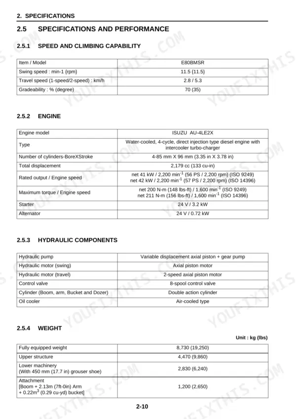
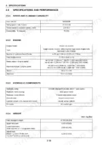
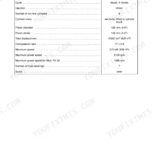
The New Holland E80BMSR workshop manual, print number 84365680B, edition 09/2010, 948 pages on the E80BMSR midi excavator. The Outline and Specifications section carries the numbers a buyer checks first: the Isuzu AU-4LE2X water-cooled 4-cycle direct injection diesel with intercooler turbocharger, rated output net 41 kW / 2,200 min-1 to ISO 9249 and net 42 kW / 2,200 min-1 to ISO 14396, fully equipped weight 8,730 kg (19,250 lbs), and an 8-spool control valve fed by a variable displacement axial piston plus gear pump.
Two drawings from the book are rendered on this page. The electric circuit diagram runs as sheets 1 to 8 starting at page 185, drawn around the Mechatro controller TCO-60-2 with every pressure sensor named at its pins, the key switch terminal table, the relays and solenoids, and every wire carrying its code, gauge and colour. The hydraulic circuit drawing on page 158 shows the main pump, hydraulic tank and main control valve with its 32.3 MPa settings, plus a parts table naming the control valve, boom, swing and dozer cylinders and pilot valve with their part numbers.
Pages 721 to 948 are a complete Isuzu 4LE2 engine manual bound in behind the machine book, with its own section numbering, from cylinder head to preheating circuit.
What's Inside This New Holland E80BMSR Manual
| System | Pages | Key Topics |
|---|---|---|
| Front Matter, Introduction & Safety Precautions | 1-10 | Print Number and Edition, How to Read the Manual, Safety Notices |
| Outline & Specifications | 11-36 | Speed and Climbing Capability, Engine Data, Hydraulic Component Types, Machine and Component Weights, Type of Crawler Shoe, Engine Characteristic Curve |
| Attachment Dimensions | 37-58 | Boom, Arm and Bucket Dimensions, Working Range, Dozer Dimensions |
| Tools & Standard Maintenance Time Table | 59-96 | Special Tools, Tightening Torques, Standard Job Times |
| Maintenance Standard & Test Procedure | 97-122 | Performance Inspection Standards, Measuring Hydraulic Pressure, Measuring Travel and Slew Performance |
| Mechatro Controller | 123-152 | Controller Inputs and Outputs, Pump Control Logic, Auto-Idle and Power Mode |
| Hydraulic System - Circuits & Operation | 153-182 | Standard Specification Hydraulic Circuit Drawing, Function and Features of the Circuit, Pump Control Operation, Boom Swing and Dozer Circuits |
| Electrical System - Circuit Diagram | 183-222 | Electric Circuit Diagram, Sheets 1 to 8, Fuse and Relay Box Layout, Sensor and Solenoid Connections, Harness Routing |
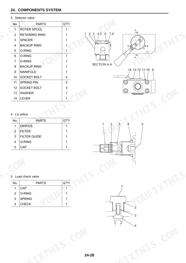
| Components System | 223-340 | Main Pump, Control Valve, Swing and Travel Motors, Pilot Valve, Swivel Joint, Cylinders |
| Air-Conditioner System | 341-390 | Refrigerant Circuit, Compressor and Condenser, Blower and Control Panel |
| Disassembly & Assembly - Attachments | 391-442 | Bucket Removal and Installation, Arm and Boom Service, Cylinder Overhaul |
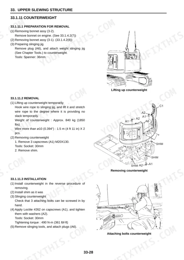
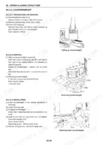
| Upper Slewing Structure | 443-572 | Cab and Canopy, Counterweight, Slew Bearing and Slew Motor, Fuel and Hydraulic Tanks, Engine Mounting |
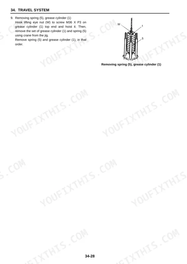
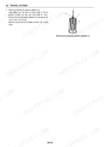
| Travel System & Undercarriage | 573-646 | Track Rollers and Carrier Rollers, Front Idler and Adjuster, Travel Motor and Reduction Gear, Track Assembly |
| Troubleshooting by Error Codes | 647-686 | Error Code List, Code-By-Code Checking Procedure, Controller Self-Diagnosis |
| Troubleshooting by Symptom | 687-720 | Fault Charts by Machine Behaviour, Circuit Isolation Steps |
| Isuzu 4LE2 Engine - General Information | 721-758 | Engine Model Identification, Service Data and Standards, Maintenance Schedule |
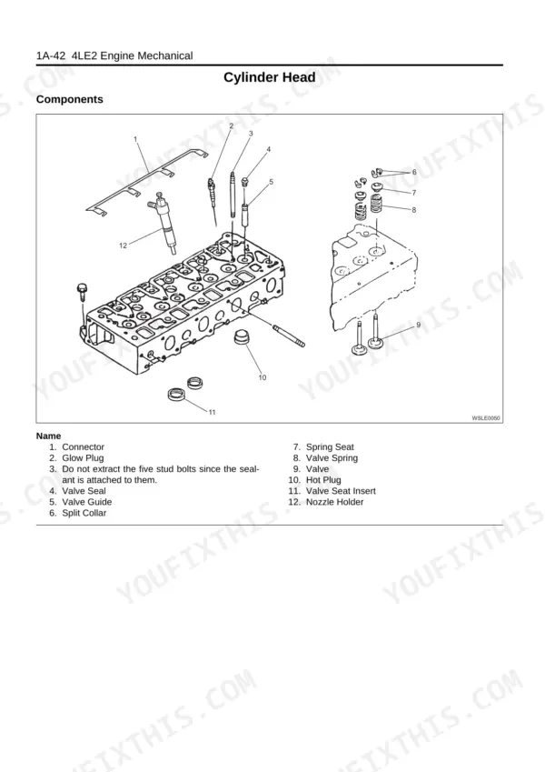
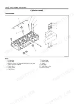
| Isuzu 4LE2 - Engine Mechanical | 759-856 | Cylinder Head and Valve Train, Piston, Connecting Rod and Crankshaft, Timing Gear Train, Assembly Clearances |
| Isuzu 4LE2 - Cooling & Fuel Systems | 857-880 | Water Pump and Thermostat, Radiator and Intercooler, Injection Pump and Injectors, Fuel Filter |
| Isuzu 4LE2 - Electrical System | 881-918 | Starter Motor, Alternator, Glow System, Engine Sensors |
| Isuzu 4LE2 - Exhaust, Lubrication, Intake & Preheating | 919-948 | Turbocharger and Exhaust, Oil Pump and Oil Cooler, Intake Manifold and EGR, Preheating Circuit |
Quick Reference Specifications
| Specification | Value | Page |
|---|---|---|
| Engine | ||
| Engine | ISUZU AU-4LE2X, water-cooled 4-cycle direct injection diesel with intercooler turbocharger | p. 30 |
| Bore x stroke, displacement | 4 cylinders, 85 mm x 96 mm (3.35 in x 3.78 in), 2,179 cc (133 cu-in) | p. 30 |
| Rated output (ISO 14396) | net 42 kW / 2,200 min-1 (57 PS / 2,200 rpm) | p. 30 |
| Maximum torque (ISO 14396) | net 211 N-m (156 lbs-ft) / 1,600 min-1 | p. 30 |
| Electrical system | ||
| Starter / alternator | 24 V / 3.2 kW and 24 V / 0.72 kW | p. 30 |
| Slew | ||
| Swing speed | 11.5 min-1 | p. 30 |
| Travel system | ||
| Travel speed, 1-speed / 2-speed | 2.8 / 5.3 km/h | p. 30 |
| Machine | ||
| Gradeability | 70% (35 degrees) | p. 30 |
| Fully equipped weight | 8,730 kg (19,250 lbs) | p. 30 |
| Upper structure weight | 4,470 kg (9,860 lbs) | p. 30 |
| Hydraulic system | ||
| Control valve | 8-spool control valve | p. 30 |
New Holland E80BMSR Common Problems This Manual Covers
The monitor throws an error code and the owner has no idea what the machine is trying to say.
Start with Troubleshooting by Error Codes, pages 647 to 686. It gives the error code list, a code-by-code checking procedure and the controller self-diagnosis. The Mechatro Controller section, pages 123 to 152, explains the inputs and outputs behind each code.
Manual Section: Troubleshooting by Error Codes p. 647The hydraulics feel weak and slow, and the machine will not pull like it used to.
Measure before swapping parts. Maintenance Standard & Test Procedure, pages 97 to 122, gives the performance inspection standards and shows how to measure hydraulic pressure and travel and slew performance. Then trace the circuit in Hydraulic System - Circuits & Operation, pages 153 to 182, which covers the circuit drawing and pump control operation.
Manual Section: Maintenance Standard & Test ProcedureThe slew is weak or noisy when swinging the upper structure.
Upper Slewing Structure, pages 443 to 572, covers the slew bearing and slew motor. The swing motor itself is described in Components System, pages 223 to 340, and the slew performance check is in Maintenance Standard & Test Procedure, pages 97 to 122.
Manual Section: Upper Slewing StructureThe engine is hard to start, especially cold, and cranks a long time before it fires.
Work through the bound-in engine manual. Isuzu 4LE2 - Electrical System, pages 881 to 918, covers the starter motor, alternator, glow system and engine sensors. The preheating circuit is in Isuzu 4LE2 - Exhaust, Lubrication, Intake & Preheating, pages 919 to 948, and the injection pump, injectors and fuel filter are in Isuzu 4LE2 - Cooling & Fuel Systems, pages 857 to 880.
Manual Section: Isuzu 4LE2 - Electrical SystemFrequently Asked Questions
The display is showing an error code. Does this manual tell me what it means and what to check?
Yes. Troubleshooting by Error Codes, pages 647 to 686, holds the error code list, a code-by-code checking procedure and the controller self-diagnosis. The Mechatro Controller section on pages 123 to 152 explains the controller inputs and outputs, pump control logic, auto-idle and power mode, so you can follow what the self-diagnosis is actually testing. p. 647
Does it cover the Isuzu engine, or only the excavator?
Both. Pages 721 to 948 are a complete Isuzu 4LE2 engine manual bound in behind the machine book: general information with service data and standards, engine mechanical work on the cylinder head, pistons, crankshaft and timing gear train, cooling and fuel systems including the injection pump and injectors, the engine electrical system with starter, alternator and glow system, and exhaust, lubrication, intake and preheating.
I have a New Holland E80. Is this the right manual for my machine?
Check your model designation first. This book is for the E80BMSR, the mid-swing-radius machine, and its cover reads E80BMSR / Workshop Manual / Print No. 84365680B / Edition 09/2010. The plain E80 is a different machine covered by a different shop manual under a different print number. If your machine is the E80BMSR, this is your book.
Are full wiring diagrams included, and are the wires identified?
Yes. The Electrical System - Circuit Diagram section on pages 183 to 222 contains the electric circuit diagram in sheets 1 to 8, plus the fuse and relay box layout, sensor and solenoid connections and harness routing. On the diagram every wire carries its code, gauge and colour, and the pressure sensors are named at the Mechatro controller pins. p. 185
Does it include tightening torques and the special tools for teardown work?
Yes. Tools & Standard Maintenance Time Table, pages 59 to 96, lists the special tools, tightening torques and standard job times. The step-by-step teardown work lives in Disassembly & Assembly - Attachments on pages 391 to 442, Upper Slewing Structure on pages 443 to 572 and Travel System & Undercarriage on pages 573 to 646.







Reviews
There are no reviews yet.