
Part of the New Holland Repair Manuals.
This is the factory repair manual for the New Holland TC5040, TC5050, TC5060, TC5070 and TC5080 combines, including the TC5080 Hillside, print number 84565976A. It works through the machine the way New Holland builds it: engine installation, the clutch and transmission, the axles, the hydrostatic drive, the brakes, the hydraulics, the steering and cab climate, the electrical system, and then the crop path itself from the header through feeding, threshing, separation, residue handling, cleaning and unloading. The hydraulic section gives each pump's pressure, displacement and flow rather than a single system figure.
What's Inside This New Holland TC5040-TC5080 (incl. Hillside) Repair Manual
| System | Pages | Key Topics |
|---|---|---|
| Introduction and Standard Torques | 8-35 | How to Use the Manual, Shop Safety, Standard Tightening Torques, Approved Fluids, Model and Serial-Number Identification |
| Engine | 36-51 | Engine Installation and Mountings, Cooling Package, Air Intake and Exhaust, Fuel Supply, Engine Ancillaries |
| Clutch | 52-67 | Main Drive Clutch and Its Control, Belt Drives, Clutch Removal and Refitting |
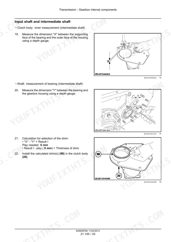
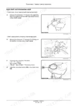
| Transmission | 68-259 | Gearbox and Range Unit, Drive Shafts and Final Drives, Transmission Control Linkage, Gearbox Strip-Down and Reassembly |
| Front Axle System | 260-287 | Driven Front Axle and Final Drives, Hubs and Bearings, Axle Service |
| Rear Axle System | 288-299 | Steering Rear Axle, Hubs, King Pins and Bearings, Rear Axle Service |
| Hydrostatic Drive | 300-379 | Hydrostatic Pump and Drive Motor, Charge Circuit, Ground Drive Control, Drive Pressure Testing and Pump Overhaul |
| Brakes and Controls | 380-413 | Service Brakes, Parking Brake, Pedal Adjustment, Bleeding the Brake Circuit |
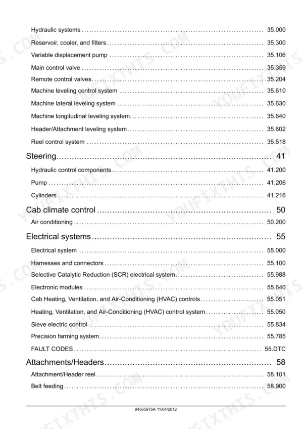
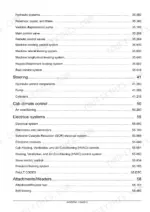
| Hydraulic Systems | 414-519 | Main, Steering and Lateral Flotation Gear Pumps with Their Pressure and Flow Specifications, Lateral Float Accumulators, Hydraulic Circuit Return and Pressure Testing, Valve and Pump Overhaul |
| Steering | 520-545 | Hydrostatic Steering Circuit and Cylinder, Steering Control Valve, Rear-Axle Steering Geometry, Fault Finding |
| Cab Climate Control | 546-605 | Heating, Ventilation and Air Conditioning, Compressor and Condenser, Refrigerant Handling, Charging and Leak Testing |
| Electrical Systems: Circuits, Harnesses and Connectors | 606-1099 | Electrical System Overview, Complete Wire Harness Drawings, Connector Component Diagrams, Fuses and Relays, Charging and Starting Circuits, Pin-Out Tables |
| Electrical Systems: Climate, Sieve Control and Precision Farming | 1100-1147 | Heating, Ventilation and Air-Conditioning Circuits, Sieve Electric Control, Precision Farming System Components and Wiring |
| Attachments and Headers | 1148-1169 | Header Attachment and Drive, Header Height and Float Control, Multi-Coupler and Header Service |
| Product Feeding | 1170-1221 | Feeder House and Elevator, Stone Trap, Feed Beater and Drive, Reversing Drive |
| Threshing | 1222-1249 | Threshing Cylinder and Concave, Concave Clearance and Rotor Speed, Threshing Drive |
| Separation | 1250-1281 | Straw Walkers and Separation Grate, Separation Drive and Bearings |
| Residue Handling | 1282-1301 | Straw Chopper and Spreader, Chaff Spreader, Residue Drive |
| Cleaning | 1302-1403 | Cleaning Shoe, Sieves and Chaffer with Their Electric Control, Cleaning Fan and Drive, Returns System, Hillside Self-Levelling Cleaning Arrangement |
| Crop Storage and Unloading | 1404-1413 | Grain Tank and Level Sensors, Unloading Auger and Drive, Unloading Control |
| Platform, Cab, Bodywork and Decals | 1414-1427 | Cab and Platform Assembly, Bodywork Panels, Glazing, Decals, Component Removal |
| Special Tool Index | 1428-1431 | Part Numbers of the Special Service Tools Each Procedure Calls for |
Quick Reference Specifications
| Specification | Value | Page |
|---|---|---|
| Main hydraulic pump | ||
| Type and rotation | Silence gear type, right-hand rotation | |
| Maximum pressure | 280 bar (4061 psi) | |
| Displacement and maximum flow, Main hydraulic pump | 16 cc/rev; 48 l/min (10.5 gal/min) at 3000 rpm maximum speed | |
| Steering circuit pump | ||
| Displacement and maximum flow, Steering circuit pump | 5.5 cc/rev; 16.5 l/min (3.6 gal/min), 280 bar maximum | |
| Lateral float accumulator | ||
| Charge pressure, Lateral float accumulator | 120 bar (1740.0 psi) | |
| Lateral float accumulator, optional | ||
| Charge pressure (Lateral float accumulator, optional) | 85 bar (1232.5 psi) | |
| Hydraulic return circuit | ||
| Return pressure | Up to 1.15 bar (17 psi) | |
| TC5040 to TC5080 | ||
| Serial number break | From 9622 onward for TC5040, TC5050, TC5060, TC5070 and TC5080 | |
New Holland TC5040-TC5080 (incl. Hillside) Common Problems This Manual Covers
Hydraulic functions are slow, or the steering goes heavy while other functions still work.
Identify which pump feeds the function before you condemn anything. The main pump gives up to 48 l/min from 16 cc per revolution, while the steering circuit has its own smaller pump at 5.5 cc per revolution and up to 16.5 l/min. Both are limited to 280 bar. Steering that fades while the rest of the machine works normally points at the steering pump or its circuit, not the main pump. The hydraulic section carries the test points and the pump overhaul.
Manual Section: Hydraulic SystemsOn a Hillside machine the lateral levelling is slow, drifts, or will not hold.
Check the accumulators first. The lateral float accumulator is charged to 120 bar, and an optional second accumulator to 85 bar, so a soft accumulator makes the levelling feel slow and spongy long before the pump is at fault. The hydraulic section gives the charging procedure and the circuit tests, and it also notes that hydraulic return pressure runs up to 1.15 bar, which is worth confirming before you chase a lazy circuit.
Manual Section: Hydraulic SystemsGrain loss over the sieves, or the sieve control not responding.
The sieves on this machine have an electric control, so a cleaning complaint can be mechanical or electrical. Work the cleaning section for the shoe, the chaffer, the fan and the returns, and check the settings against the crop. If the sieves will not move to the commanded position, switch to the electrical section, where the sieve electric control circuit sits alongside the climate and precision farming wiring, and test the motor and its harness at the connector.
Manual Section: CleaningFrequently Asked Questions
Which combines does this manual cover?
The TC5040, TC5050, TC5060, TC5070 and TC5080, plus the TC5080 Hillside self-levelling machine. The manual gives the serial-number break it applies from, machines built from 9622 onward, so check your plate before you follow a procedure. The crop-path sections cover all of them and call out the Hillside where its arrangement differs.
What are the hydraulic pump specifications?
There are separate gear pumps for separate jobs, all silence gear type with right-hand rotation and a 280 bar (4061 psi) maximum pressure at up to 3000 rpm. The main pump displaces 16 cc per revolution for a maximum of 48 l/min (10.5 gal/min). The steering circuit pump displaces 5.5 cc per revolution for a maximum of 16.5 l/min (3.6 gal/min). A third pump feeds the lateral flotation circuit.
How is the lateral flotation system pressurised?
Through accumulators. The lateral float accumulator is charged to 120 bar (1740.0 psi), with an optional accumulator charged to 85 bar (1232.5 psi). The hydraulic section covers the circuit, the accumulator charge procedure and the tests, and return oil from the hydraulics runs at up to 1.15 bar (17 psi).
Does it cover the crop path and the precision farming wiring?
Both. The crop path gets its own sections in order: attachments and headers, product feeding, threshing, separation, residue handling, cleaning with its electric sieve control, and crop storage and unloading. On the electrical side, harness drawings and connector diagrams run from page 606 to page 1099, and the climate, sieve control and precision farming circuits from page 1100 to page 1147.
How big is the manual and can I search it?
It is 1431 pages in English, a searchable and printable PDF. Search the text, print the pages you need for the bench, and keep the rest on a laptop in the workshop.
What exactly do I receive with this New Holland TC5040–TC5080 Series manual?
Immediate download of the complete 1431-page searchable Repair Manual (28 MB). Access it on any device, from a laptop at your desk to a phone in the field.
Is this New Holland TC5040–TC5080 Series Repair Manual printable?
Zero restrictions. The PDF is DRM-free. Print whatever sections you need to take out to the shop. Standard letter or A4 paper works.





Reviews
There are no reviews yet.