


This is the factory Perkins Workshop Manual for the G4.236 gasolene, natural gas and LPG engine, published by Perkins Engines Limited under publication number 601TPD06841235. It runs 102 pages and covers the spark-ignition version of the well-known 4.236 four-cylinder engine, including the AG4.236 variant built for Massey Ferguson applications.Inside you get the full workshop procedures: engine views, general data, periodical attentions, and a fault finding chart, then step by step overhaul of the cylinder head, pistons and connecting rods, cylinder block and liners, crankshaft and main bearings, timing, lubrication, cooling and fuel systems, plus the distributor and electrical system.With this PDF you can set valve clearances and ignition timing, torque the cylinder head correctly, rebuild the carburettor, renew crankshaft oil seals, and work through starting or running faults using the manual's own diagnostic chart. It is a searchable download you can print or keep on any device in the workshop.
What's Inside This Perkins G4.236 Manual
| System | Pages | Key Topics |
|---|---|---|
| Important Note | 3 | Publication Scope for Gasolene, Natural Gas & Lpg Engines, Obtaining Missing Lpg Engine Information, Perkins Engines Limited Responsibility Disclaimer |
| Engine Views | 7-11 | View of Left Hand Side of Gasolene and Lpg Engine (Lubricating Oil Filler Cap, Spark Plug, Distributor, Breather Pipe, Lubricating Oil Dipstick, Lubricating Oil Filter, Crankshaft Pulley, Drive Belt, Water Pump, Alternator Pulley, Front Lift Bracket, Thermostat Housing) |
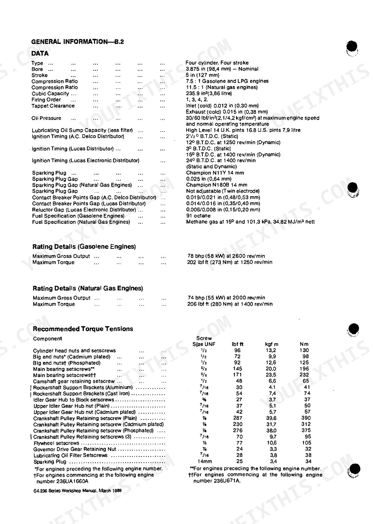
| General Information | 12-14 | Data (Type, Bore, Stroke, Compression Ratio, Cubic Capacity, Firing Order, Tappet Clearance, Oil Pressure, Lubricating Oil Sump Capacity, Ignition Timing, Sparking Plug, Sparking Plug Gap, Contact Breaker Points Gap, Reluctor Gap, Fuel Specification) |
| Periodical Attentions | 15-18 | Daily or Every 8 Hours, Every 250 Hours or 4 Months, 5000 Miles, Every 500 Hours or 12 Months, 10, 000 Miles, Every 1, 000 Hours |
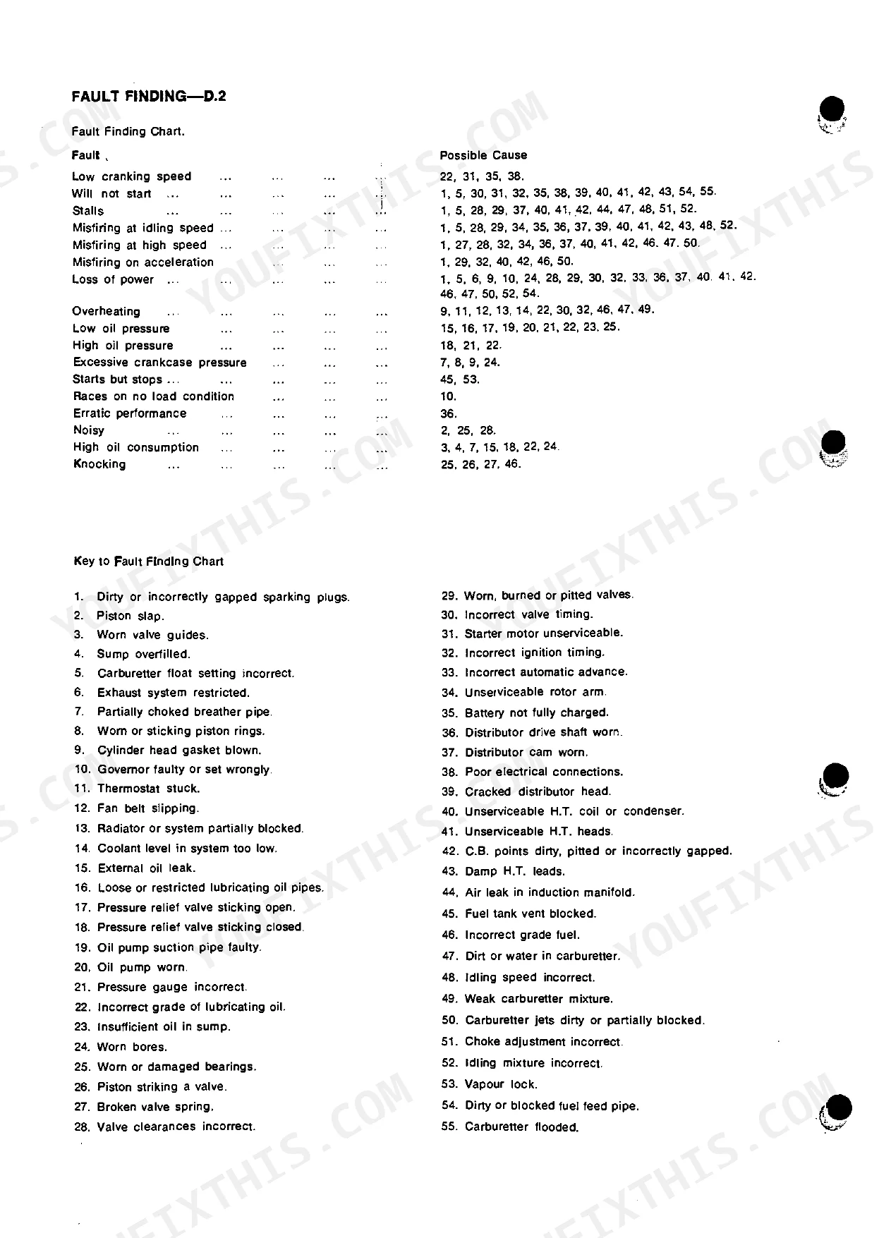
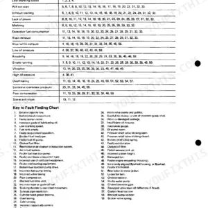
| Fault Finding | 19-20 | Fault Finding Chart (Low Cranking Speed, Will Not Start, Stalls, Misfiring at Idling Speed, Misfiring at High Speed, Misfiring on Acceleration, Loss of Power, Overheating, Low Oil Pressure, High Oil Pressure, Excessive Crankcase Pressure, Starts But Stops, Races on No Load Condition, Erratic Performance, Noisy, High Oil Consumption, Knocking) |
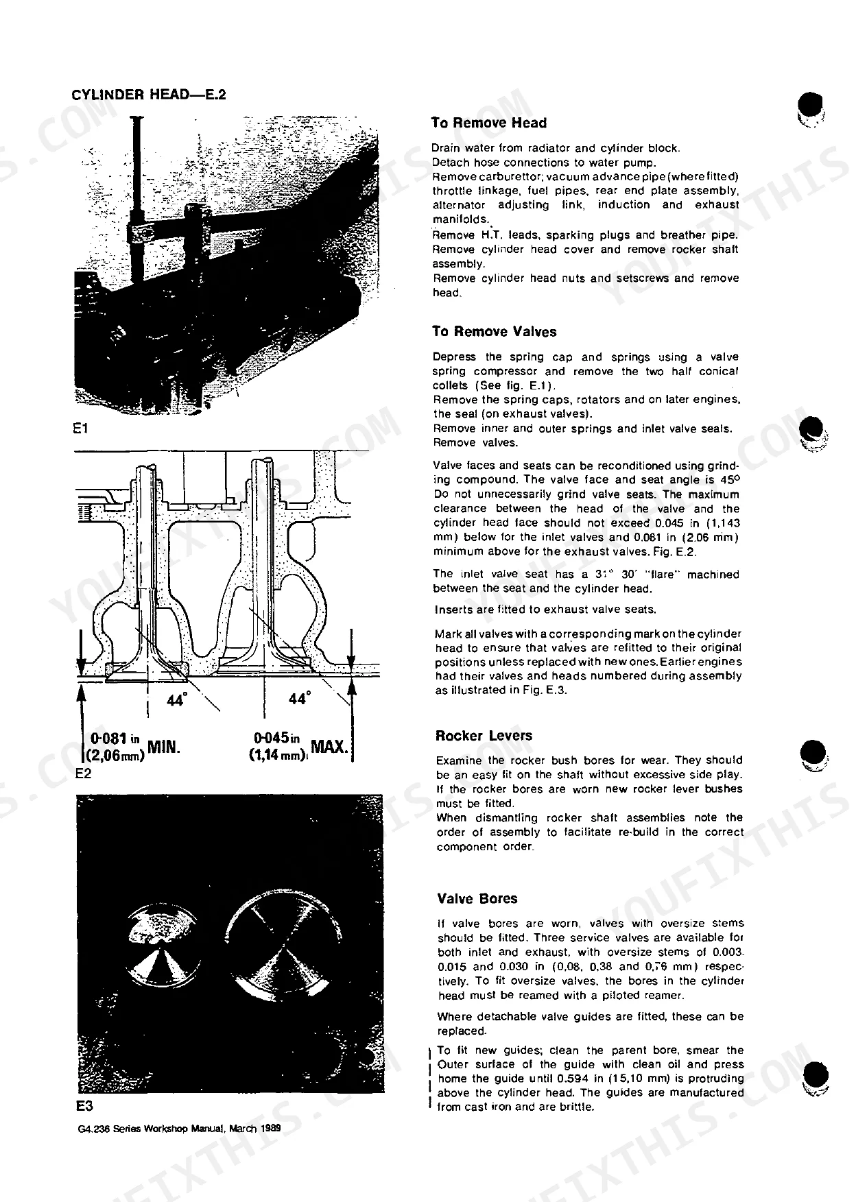
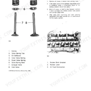
| Cylinder Head | 21-26 | To Remove Head, To Remove Valves, Rocker Levers, Valve Bores, Tappets, General, Re-Assembly |
| Pistons and Connecting Rods | 27-31 | To Remove Pistons and Connecting Rods, To Remove Gudgeon Pins, To Fit New Small End Bushes, To Assemble Piston and Connecting Rod, Fitting New Rings |
| Cylinder Block and Liners | 32-34 | Cylinder Block, Liners, Remove, Fitting, Data and Dimensions, Cylinder Liners |
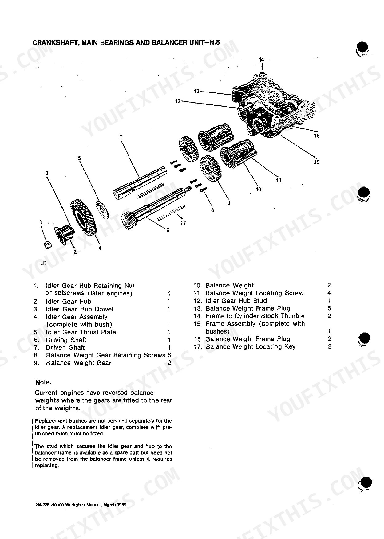
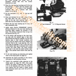
| Crankshaft, Main Bearings and Balancer Unit | 35-44 | Fitting New Main Bearings and Thrust Washers, To Remove Crankshaft, Regrinding the Crankshaft, Replacing Crankshaft, Crankshaft Rear End Oil Seal, To Fit Lip Seal in Its Housing |
| Timing Case and Drive | 45-50 | To Remove Timing Case Cover, To Renew Crankshaft Front Oil Seal, To Replace Timing Case Cover, Timing Gears, To Check Timing Gear Backlash, To Remove Idler Gear and Hub |
| Timing | 51-53 | To Reset Engine Timing, To Check Timing (Valve Timing, Ignition Timing), Ignition Timing, Static Timing (Delco Distributor, Lucas Distributor) |
| Lubrication System | 54-59 | Oil Circulation, Oil Pump, Oil Pressure, Oil Pressure Relief Valve, When to Renew the Oil |
| Cooling System | 60-64 | Data |
| Fuel System | 65-72 | Carburettor (Description, Fuel Supply System, Float Chamber), Idle System, High Speed System, Economiser System, Choke System, Dismantling, Dismantling Throttle Body |
| Flywheel and Flywheel Housing | 73-75 | To Remove Flywheel, To Renew Flywheel Ring Gear, To Refit the Flywheel, To Remove Flywheel Housing, To Refit Flywheel Housing |
| Governor and Distributor Drive | 76-79 | To Remove Governor and Distributor Drive Housing, To Remove Governor and Distributor Drive Shaft, To Replace Governor and Distributor Drive Shaft |
| Distributor | 80-83 | Condenser, Data, Setting Contact Breaker Points |
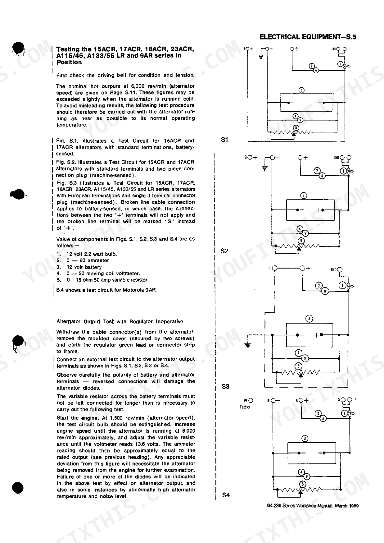
| Electrical System | 84-94 | Alternator (Models Ac5, 11 AC, 15Acr, 17Acr, 18Acr, 23Acr, A115/45, A133/55, Lr135-111, Lr135-113, Lr135-114, Le15O-160 and 9Ar, General), Maintenance, Precautions |
| Lubricating Oils | 95 | Lubricating Oils for Naturally Aspirated Engines, Lubricating Oils for Turbocharged Engines and Heavy Duty Earthmoving Equipment, Note on Mil-L-2104C Specification |
| Approved Service Tools | 96-97 | Tool Availability, Piston Ring Squeezer, Piston Height and Valve Depth Gauge, Adjustable Valve Seat Cutters, Circlip Pliers, Valve Guide Reamer .015 Inch O/Size |
| Examples of Service Facilities | 98 | - |
Quick Reference Specifications
| Specification | Value | Page |
|---|---|---|
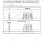
| Cylinder head nuts and setscrews torque | 96 Ibf ft (13,2 kgf m, 130 Nm) | p. 13 |
| Valve tip clearances (cold) inlet | 0.012 in (0.30 mm) | p. 23 |
| Valve tip clearances (cold) exhaust | 0.015 in (0.38 mm) | p. 23 |
| Crankshaft Rear End Oil Seal (Rope Type) strip protrusion beyond half housing joint face | 0.010/0.020 in (0,25/0,50 mm) | p. 38 |
| Crankshaft Rear End Oil Seal (Lip Type) installation depth for old type seals (first instance) | 1/8in (3.2 mm) | p. 39 |
| Engine Water Capacity | 16.5 U.K. pints, 19.8 U.S. pints (9.36 litres) | p. 64 |
| Thermostat Opening Temperature | 76/80°C (168.6/176°F) | p. 64 |
| Engine Bore | 3.875 in (98.4 mm) | p. 13 |
| Engine Stroke | 5 in (127 mm) | p. 13 |
| Compression Ratio (Gasolene and LPG engines) | 7.5 : 1 | p. 13 |
| Tappet Clearance (Inlet cold) | 0.012 in (0.30 mm) | p. 13 |
| Lubricating Oil Sump Capacity (less filter) | 7.9 litre (14 U.K. pints, 16.8 U.S. pints) | p. 13 |
Perkins G4.236 Common Problems This Manual Covers
Hard starting and rough running
Fuel-system faults are the most cited G4.236 complaint, showing up as hard starting, rough idle, and loss of power. The Fuel System section covers the carburettor, float chamber, idle and high speed circuits, choke, and dismantling for a full clean or rebuild.
Manual Section: Fuel System p. 65Oil leaks at the rear main seal
Oil leaks are common on these older engines, often at the crankshaft rear end oil seal and main bearing area. This section covers fitting new main bearings and thrust washers and renewing both rope and lip type rear end oil seals.
Manual Section: Crankshaft, Main Bearings and Balancer Unit p. 35Head gasket failure
Community reports list head gasket failure as a common issue, leading to coolant loss, cylinder contamination, and overheating. The Cylinder Head section covers head removal, valve and rocker work, and correct re-assembly to reseal the top end.
Manual Section: Cylinder Head p. 21Cooling-system corrosion and overheating
Using unsuitable coolant lets corrosion attack the cooling system and can deteriorate cooling components, causing overheating. The Cooling System section gives the cooling data and description, including the thermostat opening temperature and water capacity.
Manual Section: Cooling System p. 60Misfiring and ignition faults
Spark-ignition G4.236 engines can misfire at idle, high speed, or on acceleration when ignition timing or the distributor drift out. The Timing section covers resetting engine timing and static ignition timing for both Delco and Lucas distributors.
Manual Section: Timing p. 51Engine will not start or stalls
Low cranking speed, no-start, stalling, and erratic running are frequent owner symptoms with several possible causes. The Fault Finding chart lists these symptoms against likely causes so you can work through a no-start methodically before pulling parts.
Manual Section: Fault Finding p. 19Frequently Asked Questions
Which engines does this manual cover?
It covers the Perkins G4.236 gasolene, natural gas, and LPG engine, the spark-ignition version of the 4.236 four-cylinder. It also applies to the AG4.236 designation built for Massey Ferguson applications, with those differences noted where relevant.
What is the cylinder head torque for the G4.236?
The manual specifies 96 lbf ft (130 Nm) for the cylinder head nuts and setscrews. The Cylinder Head section covers head removal and correct re-assembly, so you can follow the proper tightening sequence when refitting the head. p. 21
How do I diagnose a no-start or misfire?
The Fault Finding chart lists symptoms such as low cranking speed, will not start, stalling, and misfiring at idle or high speed, each matched to likely causes. It gives you a structured starting point before dismantling anything. p. 19
How do I get the manual after buying?
You download the PDF straight after purchase, so there is no waiting for shipping and nothing physical to store. Save it to your device and reopen or reprint it whenever you service the engine.
Is this Perkins Engines Limited G4.236 Workshop Manual a digital download?
A 102-page searchable PDF lands in your account the moment checkout clears. Open it on a laptop, tablet, or phone, whatever you keep nearby while working.
Can I print this Perkins Engines Limited G4.236 manual?
Print as many copies as you like; there are no restrictions. Plenty of mechanics just run off the one section they happen to be working from.
Does this Perkins Engines Limited G4.236 manual have electrical diagrams?
Yes. You'll find full electrical schematics with wire routing diagrams, connector identification, and circuit descriptions.

Reviews
There are no reviews yet.