
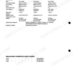
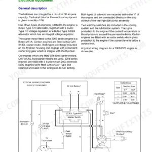
Rebuilding one of these big diesels? This 192-page Perkins 2806C-E18 TAG1, TAG2, TAG3 Shop Manual PDF (OEM #TPD 1517E) walks you through complete disassembly and rebuild of the 6-cylinder turbocharged engine, straight from the factory. You get a full chapter of recommended torque figures, wear-limit specifications for valves, guides, liners, and main bearings, plus step-by-step procedures for the cylinder head, pistons and connecting rods, crankshaft seals, gear train timing, turbocharger, electronic fuel injector units, and coolant pump. Special tool lists and ECM service round it out. Set inlet tappet clearance to 0.38 mm, exhaust to 0.76 mm, and check the nominal 145 mm bore against liner limits before you order parts. Forum threads won't rebuild your bottom end. Bookmarked chapters and a live text layer take you straight to any spec; download it and get back on the crank.
What's Inside This Perkins 2806C-E18 TAG1–TAG3 Manual
| System | Pages | Key Topics |
|---|---|---|
| General Information | 11-16 | Safety Precautions |
| Specifications | 17-36 | Basic Engine Data, Rocker Assemblies, Valves, Valve Guides, Valve Springs, Valve Seat Inserts, Cylinder Head, Camshaft and Bearings |
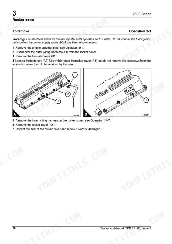
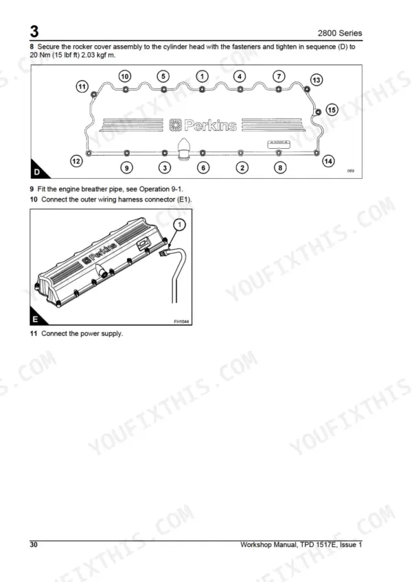
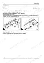
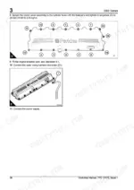
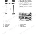
| Cylinder Head Assembly | 37-66 | Rocker Cover, Rocker Lever and Rocker Shaft Assemblies, Valve Springs, Valves |
| Pistons and Connecting Rod Assemblies | 67-74 | Pistons and Connecting Rod, Piston Cooling Jets |
| Crankshaft Assembly | 75-88 | Crankshaft, Early Type of Crankshaft Front Seal and Wear Sleeve, Early Type of Crankshaft Rear Seal and Wear Sleeve, New Type of Front Crankshaft Oil Seal |
| Gear Case and Drive Assembly | 89-100 | Gear Case Cover, Camshaft Gear, Adjustable Idler Gear and Axle, Main Idler Gear, Compound Idler Gear, Gear Case |
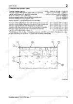
| Crankcase and Cylinder Liners | 101-106 | Front Engine Support, Cylinder Liners |
| Engine Timing | 107-110 | TDC Setting, Timing Gears, Camshaft Gear, Crankshaft Gear, Idler Gear, Backlash |
| Aspiration System | 111-124 | Breather Pipe, Air Filter Assembly, Air Intake System, Charger Cooler Pipes, Turbocharger, Exhaust Manifold |
| Lubrication System | 125-134 | Oil Filter Element, Oil Filter Head, Sump, Lubricating Oil Pump |
| Fuel System | 135-144 | Electronic Fuel Injector Units, Fuel Priming Pump, Fuel Transfer Pump, Drive for the Fuel Transfer Pump, Fuel Filter Header, Low Pressure Fuel System |
| Cooling System | 145-164 | Radiator, Fan Drive Assembly, Engine Oil Cooler, Thermostats and Thermostat Housing, Coolant Pump |
| Flywheel and Housing | 165-170 | Flywheel, Flywheel Housing |
| Electrical Equipment | 171-182 | Starter Motor, Alternator, Electronic Control Module, Inner Wiring Harness of the Rocker Cover, Temperature Sensor, Camshaft and Crankshaft Speed Position Sensor |
| Auxiliary Equipment | 183-184 | Oil Sample Valve |
| Special Tools | 185-192 | List of Special Tools |
Quick Reference Specifications
| Specification | Value | Page |
|---|---|---|
| Thermostat opening distance | 10,4 mm (0.41 in) | p. 160 |
| Nominal bore | 145 mm | p. 17 |
| Nominal stroke | 183 mm | p. 17 |
| Inlet valve tappet clearance | 0.38 mm | p. 45 |
| Exhaust valve tappet clearance | 0.76 mm | p. 45 |
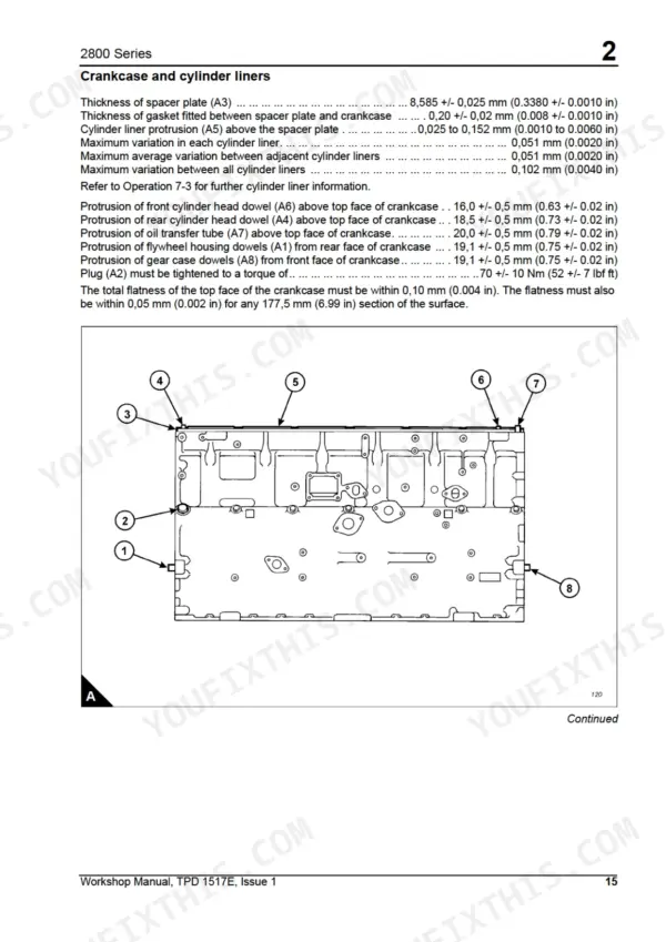
| Cylinder liner protrusion | 0.025 to 0.152 mm | p. 104 |
| Engine dry weight | 2050 kg | p. 16 |
| Cylinder head bolt torque (final) | 450 Nm | p. 51 |
| Main bearing cap bolt torque | 260 Nm | p. 77 |
Perkins 2806C-E18 TAG1–TAG3 Common Problems This Manual Covers
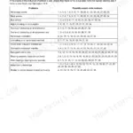
Perkins 2806C-E18 loud top-end tapping noise at idle, gets worse as the engine warms up
Remove the rocker cover and check valve tip clearances with the engine cold. Set inlet valves to 0.38 mm and exhaust valves to 0.76 mm using the procedure on page 45. Inspect rocker levers and shaft for wear while the cover is off, and replace any broken valve springs found.
Manual Section: Cylinder Head Assembly p. 45Engine overheats under full load, coolant temperature keeps climbing even with radiator clean and fan turning
Test the thermostats before condemning the water pump. Remove them and heat-test in water; a good thermostat must open to 10,4 mm (0.41 in) travel, spec on page 160. Check coolant level, pressure-test the system for leaks, and inspect the coolant pump using the cooling system procedures starting on page 145.
Manual Section: Cooling System p. 160Low oil pressure warning at hot idle after oil and filter change, pressure recovers at higher RPM
Verify oil level and grade first, then replace the filter element and inspect the sump strainer for restriction using the lubrication system procedures on page 125. Check the relief valve for sticking and inspect the oil pump for wear. If bearings are suspect, torque main bearing cap bolts to 260 Nm on reassembly.
Manual Section: Lubrication System p. 125Heavy crankcase breathing with blue exhaust smoke and oil consumption climbing steadily on a high-hour engine
Check the breather pipe for blockage and inspect the turbocharger oil seal before pulling pistons. If blowby continues, remove pistons and connecting rods per page 67, measure ring wear, and inspect the liners. When refitting liners, verify protrusion falls between 0.025 and 0.152 mm, spec on page 104.
Manual Section: Crankcase and Cylinder Liners p. 104Coolant level dropping with no external leaks, white smoke on startup, oil turning milky on the dipstick
Pressure-test the cooling system and inspect the cylinder head gasket. Remove the head using the procedure starting on page 47, check the face for distortion, and inspect liner seating. On reassembly, tighten cylinder head setscrews in the correct sequence to a final torque of 450 Nm (333 lbf ft), page 51.
Manual Section: Cylinder Head Assembly p. 51Frequently Asked Questions
What are the replacement specifications for the fuel filter element?
To replace the fuel filter elements, remove the filter housings and elements from the fuel filter header. Renew the fuel filter elements in the primary and secondary fuel filter canisters as described in the User's Handbook TPD 1516. p. 142
What is the correct torque for the cylinder head setscrews?
The cylinder head setscrews must be tightened in three stages. First, tighten to 270 Nm (200 lbf ft) 27,5 kgf m, then to 450 Nm (333 lbf ft) 45,8 kgf m, and finally tighten again to 450 Nm (333 lbf ft) 45,8 kgf m. p. 51
What are the tappet clearance specifications for the inlet and exhaust valves?
The correct clearance for the inlet valve is 0,38 mm (0.015 in) and 0,76 mm (0.030 in) for the exhaust valve. These measurements are taken between the rocker levers and the top of the valve bridge pieces with the engine cold. p. 45
What is the lubricating oil pressure at rated speed?
The lubricating oil pressure at rated speed is 4,2 bar (60.9 PSI). p. 17
What is the procedure for checking the cylinder liner protrusion?
Cylinder liner protrusion is measured from the top of the cylinder liner to the top of the spacer plate using the special tool GE50002. The correct specification is 0,025 to 0,152 mm (0.001 to 0.006 in). p. 104
What do I get after purchasing this Perkins 2806C-E18 TAG1 manual?
This is a 192-page searchable PDF ready for immediate download. Works on any device, so pull it up on your phone while you're under the hood. No shipping, no waiting.
Is this Perkins 2806C-E18 TAG1 manual print-friendly?
Yes. The PDF has no DRM restrictions, so print any page or section you need for your shop. Works with any standard printer.
Reviews
There are no reviews yet.