
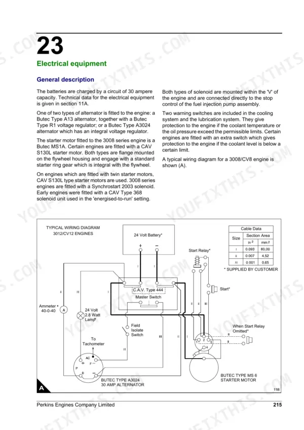
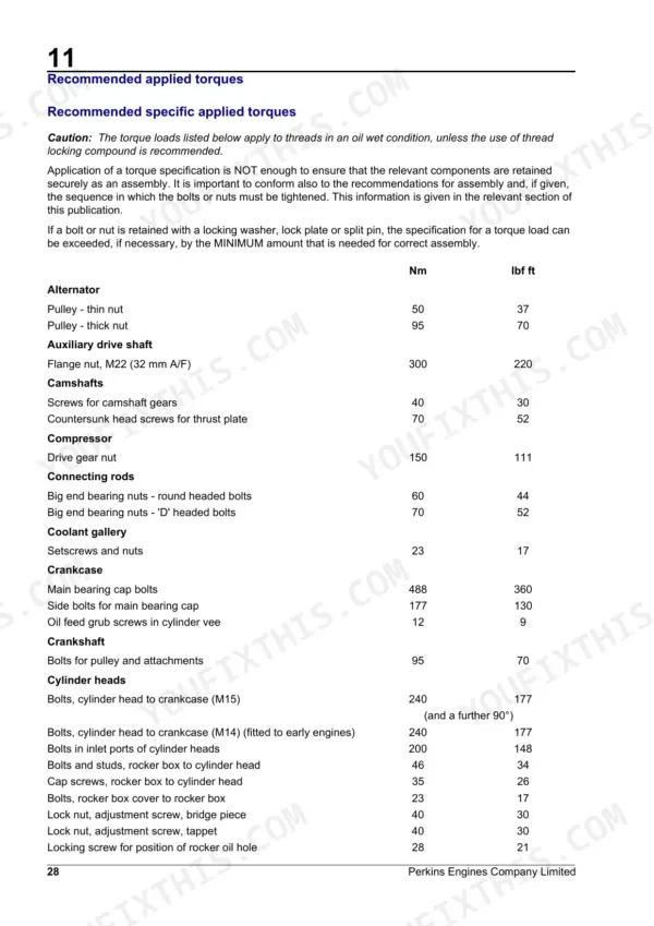
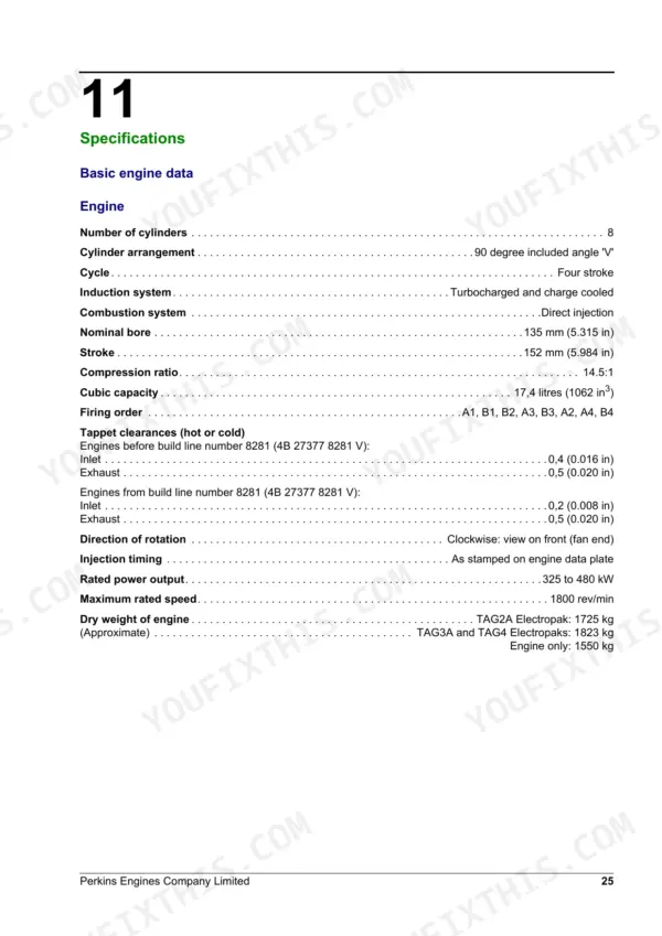
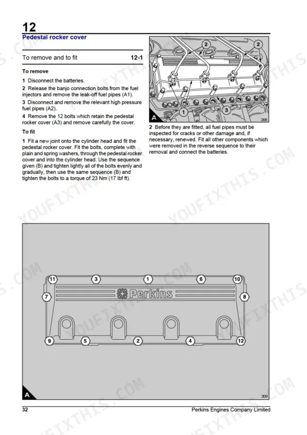
Perkins printed this one as TSD 3430, issue 2, and it runs 256 pages on the 3008 and CV8 diesel V8. Teardown and rebuild are covered end to end: cylinder heads, pistons and connecting rods, crankshaft, timing gears and case, camshafts and engine timing, the twin turbochargers and air-to-air charge coolers, the eight-element Bosch in-line injection pump, cooling, and the flywheel housing. Fits and clearances sit in their own blocks beside the procedures, so you measure as you go instead of hunting a spec table twenty pages away. Torque the M15 cylinder head bolts to 240 Nm plus a further 90 degrees; injector clamp cap screws go to 60 Nm. Check the build line before you set valves: engines from number 8281 run 0,2 mm inlet clearance, earlier ones 0,4 mm. Page 215 carries a typical wiring diagram alongside its cable-data table. Native text layer and 63 bookmarks, so a search for any spec lands you on the page.
What's Inside This Perkins 3008 / CV8 Manual
| System | Pages | Key Topics |
|---|---|---|
| General Information | 15-24 | Introduction, Bank and Cylinder Bore Identification, Engine Identification, Safety, Useful Information |
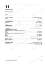
| Specifications | 25-27 | Basic Engine Data (Cooling System, Fuel System, Lubrication System, Induction and Exhaust Systems, Electrical Equipment, Auxiliary Equipment) |
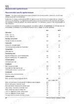
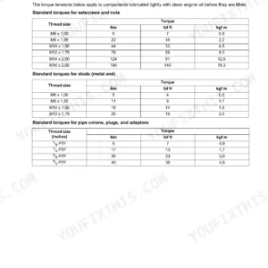
| Recommended Applied Torques | 28-30 | Recommended Specific Applied Torques, Recommended Nominal Applied Torques |
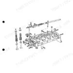
| Cylinder Head Assembly | 31-57 | Pedestal Rocker Assembly, Rocker Boxes |
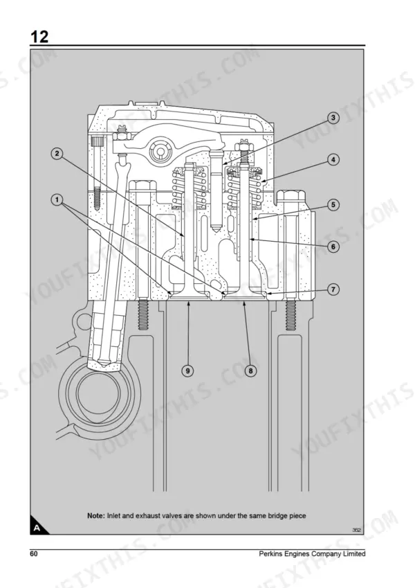
| Fits and Clearances | 58-60 | Rocker Boxes, Cylinder Heads and Valve Gear |
| Pistons and Connecting Rods | 61-76 | Big End Bearings, Piston and Connecting Rod Assembly, Piston Rings |
| Crankshaft Assembly | 77-92 | Crankshaft Pulley, Front Oil Seal, Rear Oil Seal Assembly |
| Timing Gears and Timing Case | 93-104 | Timing Case, Auxiliary Drive Assembly, Double Idler Gear |
| Cylinder Block Assembly | 105-116 | Crankcase, Cylinder Liners |
| Camshafts and Engine Timing | 117-122 | Camshafts (Remove and Fit, Clean and Inspect), Valve Timing Check, Fuel Injection Pump Timing Check and Adjustment |
| Induction and Exhaust System | 123-142 | Air Cleaners, Induction Manifolds, Exhaust Manifolds, Turbocharger |
| Lubrication System | 143-151 | Filter Canisters, By-Pass Filter Assembly, Lubricating Oil Pump |
| Fuel System | 152-193 | Fuel Injectors, Fuel Lift Pump, Fuel Injection Pump and Governor |
| Cooling System | 194-210 | Radiator, Coolant Pump, Thermostat |
| Flywheel and Flywheel Housing | 211-214 | Flywheel (Remove and Fit, Inspect), Starter Ring Renewal, Flywheel Housing Remove and Fit |
| Electrical Equipment | 215-238 | Alternator Drive Belt, Alternator, Starter Motor |
| Auxiliary Equipment | 239-242 | Compressor |
| Running-In and Test | 243-244 | Engine Running, Lubricating Oil Consumption |
| Special Tools | 245-256 | Valve Spring Compressor, Fuel Injector Sleeve Tools, Cylinder Head Lift Adaptor, Cylinder Liner Tools, Crankshaft Bearing Remover, Torque Wrenches |
Quick Reference Specifications
| Specification | Value | Page |
|---|---|---|
| Bolts, cylinder head to crankcase (M15) | 240 Nm (177 lbf ft) and a further 90° | p. 28 |
| Bolts, cylinder head to crankcase (M14) (fitted to early engines) | 240 Nm (177 lbf ft) | p. 28 |
| Fuel filter head: adaptors, filter element | 54 Nm (40 lbf ft) | p. 29 |
| Fuel injectors: cap screws, injector clamp | 60 Nm (44 lbf ft) | p. 29 |
| Fuel injectors: cap nut, nozzle | 80 Nm (60 lbf ft) | p. 29 |
| Turbochargers: mounting nuts | 46 Nm (34 lbf ft) | p. 30 |
| Turbochargers: vee band clamp (captive T-bolt type) | 17 Nm (12 lbf ft) | p. 30 |
| Coolant pump: bearing lock nut | 100 Nm (74 lbf ft) | p. 29 |
| Coolant pump: drive gear nut | 88 Nm (65 lbf ft) | p. 29 |
| By-pass filter rotor nut torque | 20 Nm (15 lbf ft) | p. 146 |
| Sump drain plug (direct into sump; 115 Nm with thread insert) | 47 Nm (35 lbf ft) | p. 146 |
| Fuel injection pump: adjusting plate setscrews | 46 Nm | p. 29 |
Perkins 3008 / CV8 Common Problems This Manual Covers
Engine misfires or runs erratically after fuel filter replacement, dies at idle
Bleed air from the low pressure fuel system first, following the procedure on page 192, then crack the high pressure pipes at the injectors while cranking. If the misfire stays, pull the injectors and bench test them; opening pressure should be 243 bar. Torque leak-off connections to 27 Nm on refit so air cannot be drawn back in.
Manual Section: Fuel System Air Elimination p. 192White or blue exhaust smoke on cold start that continues after warm-up under load
Test the injectors first; check spray atomisation and nozzle leakage, and refit nozzle cap nuts at 80 Nm, listed on page 155. If the injectors pass, inspect the turbocharger for oil seal leakage; measure rotor shaft end-float, which must stay between 0,025 and 0,102 mm before the seals can hold oil out of the intake.
Manual Section: Fuel Injector Fault Diagnosis p. 155Low oil pressure warning at idle when hot, pressure recovers at higher rpm
Check oil level and grade first; fuel dilution or the wrong viscosity drops hot idle pressure fast. Drop the sump and clean the strainer for sludge restriction; torque sump bolts to 55 Nm on refit, page 147. Fit new filter elements, torque the adaptors to 54 Nm, then inspect the oil pump for wear if pressure stays low.
Manual Section: Lubrication System p. 143Coolant temperature rises under sustained load, engine loses coolant with no visible leak
Check coolant level; the system holds 68.2 litres and a low fill overheats quickly under load. Inspect the water pump for a worn impeller; impeller to casing clearance should be 0,35 mm, listed on page 199. Test the thermostat, then pressure-test the system for head gasket or cylinder liner leakage into the combustion chambers.
Manual Section: Cooling System p. 199Frequently Asked Questions
What are the torque specifications for the Perkins 3008 cylinder head bolts?
For M15 cylinder head bolts, tighten them in stages to 80 Nm, 160 Nm, and 200 Nm. Finally, tighten the bolts shown in black circles to 240 Nm and then an additional 90 degrees. Bolts in the inlet ports (white circles) should be tightened to 200 Nm. p. 42
How do I bleed air from the fuel system on a Perkins 3008 engine?
To bleed the low pressure system, loosen the banjo bolt at the low pressure relief valve by one or two turns and operate the priming plunger on the fuel lift pump until fuel flows free of air. For the high pressure system, move the stop control to the RUN position, use the starter to turn the engine, and loosen the nut of the high pressure fuel pipe at each injector until fuel flows free of air. p. 192
How do I check or adjust the fuel injection pump timing on a Perkins 3008/CV8?
To check the timing, rotate the engine until the injection timing mark on the flywheel aligns with the pointer while the B1 piston is at TDC on its compression stroke. If the timing mark on the pump hub does not align with the pointer, loosen the bolts on the drive coupling and rotate the hub until the marks align, then tighten the bolts. p. 120
How do I fix a Perkins 3008 that cranks slowly or will not start in cold weather?
Check battery connections first; torque the main starter cable terminal nut to 34 to 41 Nm. Test starter motor pinion clearance with the 4.76 mm gauge described on page 235, and verify the solenoid switch operating sequence. If the solenoid clicks but the motor will not spin, measure pull-in winding resistance against the 1.34 ohm spec. p. 235
How quickly can I access this Perkins 3008 manual after buying?
You get a 256-page searchable PDF that downloads instantly after checkout. Open it on your laptop, tablet, or phone, and bring it right to the shop floor.
Are there any print restrictions on this Perkins 3008 manual?
You can. The PDF is unlocked and carries no copy protection, so print the sections you want and keep the file as your backup.
Can I find wiring schematics in this Perkins 3008 manual?
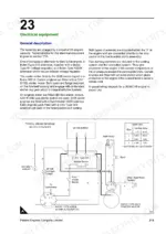
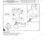
Yes. The Electrical Equipment section carries a typical wiring diagram for the 3008/CV8 engine on page 215, printed alongside a cable-data table giving the size and section area of each cable, plus circuit descriptions for the alternator, starter motor, stop solenoid and the engine protection switches. p. 215
Reviews
There are no reviews yet.