
Need factory data for your Perkins Phaser 135 Ti? This 212-page Model AL Workshop Manual PDF (OEM TPD 1356E) covers the complete 4 cylinder diesel engine, from cylinder head to flywheel housing. You get standard and special torque tensions, compression test data, and full engine timing procedures including the flywheel pin and reverse pin methods. Inside: step-by-step rebuilds for the Bosch EPVE fuel injection pump, a turbocharger fault section, and page after page of crankshaft, piston, and cylinder liner procedures. Set cold valve tip clearances at 0.20 mm inlet and 0.45 mm exhaust, then torque the cylinder head setscrews to 110 Nm. No more chasing specs through forum threads. Bookmarked with a full text layer; search any spec by keyword, pull it up on your phone in the shop, and get back to wrenching.
What's Inside This Perkins Phaser 135 Ti, Model AL Manual
| System | Pages | Key Topics |
|---|---|---|
| General Information | 1-20 | Introduction, Engine Identification, Safety Precautions, Engine Lift Equipment, Viton Seals, Powerpart Recommended Consumable Products |
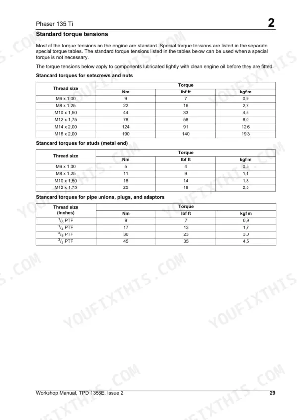
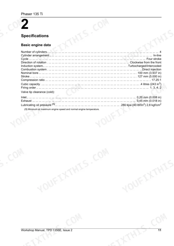
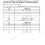
| Specifications | 21-42 | Basic Engine Data, Data and Dimensions, Thread Sealant, Standard Torque Tensions, Special Torque Tensions, Compression Test Data |
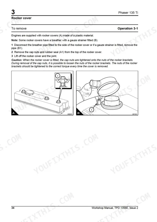
| Cylinder Head Assembly | 43-66 | Rocker Cover, Rocker Assembly, Valve Tip Clearances |
| Piston and Connecting Rod Assemblies | 67-84 | Big End Bearing, Piston and Connecting Rod, Piston Rings, Piston and Connecting Rod Assembly, Piston and Piston Rings, Connecting Rod, Small End Bush, Piston Cooling Jets |
| Crankshaft Assembly | 85-98 | Crankshaft Pulley and Damper, Rear Oil Seal Assembly, Thrust Washers, Main Bearings, Crankshaft |
| Timing Case and Drive Assembly | 99-116 | Timing Case Cover, Front Oil Seal, Idler Gear and Hub, Idler Gear and Hub for the Bendix Compressor, Fuel Pump Gear, Camshaft Gear, Crankshaft Gear, Timing Case |
| Cylinder Block Assembly | 117-126 | Cylinder Block, Cylinder Liner |
| Engine Timing | 127-134 | Flywheel and Pin Method, Reverse Pin Timing, Alternative Method, Valve Timing, Fuel Injection Pump Timing |
| Aspiration System | 135-146 | Turbocharger, Turbocharger Faults, Open Engine Breather |
| Lubrication System | 147-158 | Engine Lubrication System Flow Diagram, Filter Canister, Filter Head, Sump, Oil Strainer and Suction Pipe, Lubricating Oil Pump, Relief Valve |
| Fuel System | 159-178 | Fuel Filter Element, Atomisers, Fuel Lift Pump, Bosch Epve Fuel Injection Pump |
| Cooling System | 179-186 | Thermostats, Coolant Pump, Lubricating Oil Cooler |
| Flywheel and Housing | 187-190 | Flywheel, Ring Gear, Flywheel Housing |
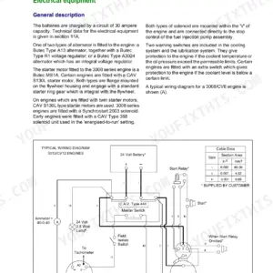
| Electrical Equipment | 191-200 | Alternator Fault Diagnosis |
| Auxiliary Equipment | 201-206 | Power Steering Pump, Exhauster |
| Special Tools | 207-212 | List of Special Tools |
Quick Reference Specifications
| Specification | Value | Page |
|---|---|---|
| Valve tip clearance (cold) - Inlet | 0,20 mm (0.008 in) | p. 21 |
| Valve tip clearance (cold) - Exhaust | 0,45 mm (0.018 in) | p. 21 |
| Cylinder head setscrew torque | 110 Nm (80 lbf ft) 11,1 kgf m | p. 55 |
| Cylinder head setscrew further turn (short/medium/long) | 150° / 180° / 210° | p. 55 |
| Nominal bore | 100 mm (3.937 in) | p. 21 |
| Stroke | 127 mm (5.000 in) | p. 21 |
| Compression ratio | 17.25:1 | p. 21 |
| Cubic capacity | 4 litres (243 in3) | p. 21 |
| Firing order | 1, 3, 4, 2 | p. 21 |
| Lubricating oil pressure (minimum at max speed) | 280 kPa (40 lbf/in2) 2,8 kgf/cm2 | p. 21 |
| Starter motor cable resistance (12V) | 0,0017 ohms | p. 36 |
| Starter motor cable resistance (24V) | 0,0034 ohms | p. 36 |
Perkins Phaser 135 Ti, Model AL Common Problems This Manual Covers
Perkins Phaser 135 Ti cranks too slowly and will not start, worse in cold weather
Check battery terminals and ground straps for corrosion, then measure starter cable resistance: on 12 volt systems it must not exceed 0.0017 ohms, or 0.0034 ohms on 24 volt systems, per the electrical data on page 36. Verify the oil grade suits ambient temperature. If cranking stays slow, test the starter motor per the Electrical Equipment section on page 191.
Manual Section: Electrical Equipment p. 191Engine runs hot under load and coolant temperature gauge climbs into the red
Check the radiator core for debris and clean the air passages. Inspect the fan for damaged blades. Remove and test both thermostats in heated water, then check the coolant pump for leaks and bearing play, following the Cooling System procedures starting on page 179. Set valve tip clearances cold to 0.20 mm inlet and 0.45 mm exhaust.
Manual Section: Cooling System p. 179Low compression on one or more cylinders, engine lacks power and smokes on cold start
Adjust valve tip clearances cold to 0.20 mm (0.008 in) inlet and 0.45 mm (0.018 in) exhaust, per the specifications on page 21. If compression stays low, remove the cylinder head using the service procedures on page 44 and inspect the face for cracks and distortion. Torque the head setscrews to 110 Nm on reassembly, per page 55.
Manual Section: Cylinder Head Assembly p. 43Engine misfires at idle, runs rough under load, black smoke from the exhaust
Replace the fuel filter element and bleed all air from the low pressure system. Check the fuel pipes for restriction and drain any water from the tank. Test atomiser spray pattern and seat leakage per the Fuel System section starting on page 159. Before condemning the injection pump, confirm valve tip clearances are correct at 0.20 mm inlet, 0.45 mm exhaust.
Manual Section: Fuel System p. 159Frequently Asked Questions
What is the torque specification for the cylinder head setscrews?
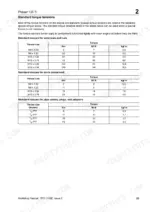
The cylinder head setscrews must be tightened in the specified sequence to 110 Nm (80 lbf ft) 11,1 kgf m. Following this, they must be tightened a further part of a turn based on their length: 150° for short setscrews, 180° for medium, and 210° for long setscrews. p. 55
What is the torque specification for the atomiser gland nut?
The atomiser gland nut should be tightened gradually and evenly to 30 Nm (23 lbf ft) 3,0 kgf m. p. 164
What are the replacement specifications for the fuel filter element?
The fuel filter element is a single element type. When replacing, ensure that the inner seal (A3) and outer seal (A4) are in position on top of the canister, and tighten the new canister by hand only. p. 161
What are the replacement specifications for the lubricating oil filter canister?
The oil filter is a full flow, screw-on type canister. When replacing, add clean engine lubricating oil to the new canister before fitting, and tighten it by hand only. p. 149
What is the correct valve tip clearance for the engine?
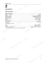
The valve tip clearance (cold) is 0,20 mm (0.008 in) for inlet valves and 0,45 mm (0.018 in) for exhaust valves. p. 21
What exactly do I receive with this Perkins Phaser 135 Ti Workshop Manual?
Immediate download of the complete 212-page searchable Workshop Manual. Access it on any device, from a laptop at your desk to a phone in the field.
Is printing allowed for this Perkins Phaser 135 Ti Workshop Manual?
Yes. Print the pages or sections you need for your own shop use. Any standard printer works.
Reviews
There are no reviews yet.