
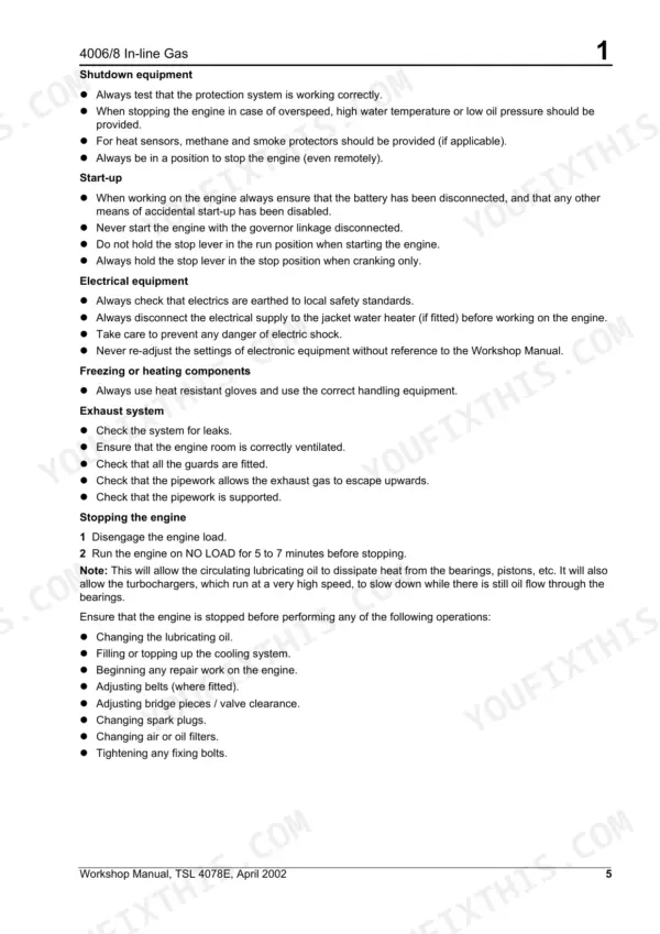
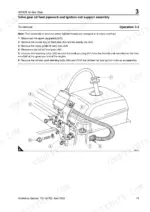
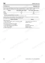
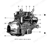
This 166-page Perkins workshop manual covers the 4006 and 4008 in-line gas engines of the 4000 Series, including the TESI 90 HC, 140 HC, 140 LC and 200 LC variants. It takes the engine apart and puts it back together: cylinder head assembly with its detonation-sensor rail, pistons and connecting rods, crankshaft and cylinder liners, gearcase and timing gears, camshaft and cam followers, the turbocharged aspiration system, the gas system with its control valves, lubrication and cooling, flywheel and housing, and the electrical system with its magnetic sensors. Bore 160 mm, stroke 190 mm, with the 9.5:1 (LC) and 11.5:1 (HC) compression ratios and the special-tool list at the back.
What's Inside This Perkins 4006, 4008 (4000 Series) Manual
| System | Pages | Key Topics |
|---|---|---|
| General Information | 1-8 | Introduction, Engine Identification, Safety Precautions, Practical Information for Cleaning Components |
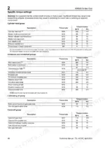
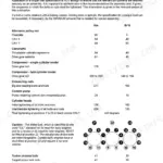
| Specifications | 9-14 | Basic Engine Data, General, Engine Weight, Specific Torque Settings, Cylinder Head Group, Crankcase and Crankshaft Groups, Lubricating Oil Pump, Camshaft Group |
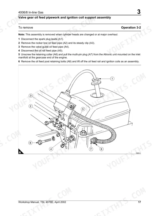
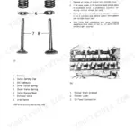
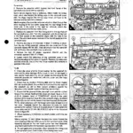
| Cylinder Head Assembly | 15-42 | Detonation Sensor Wiring Rail, To Remove and to Fit, Valve Gear Oil Feed Pipework and Ignition Coil Support Assembly, To Remove, To Fit, Inlet and Exhaust Manifolds |
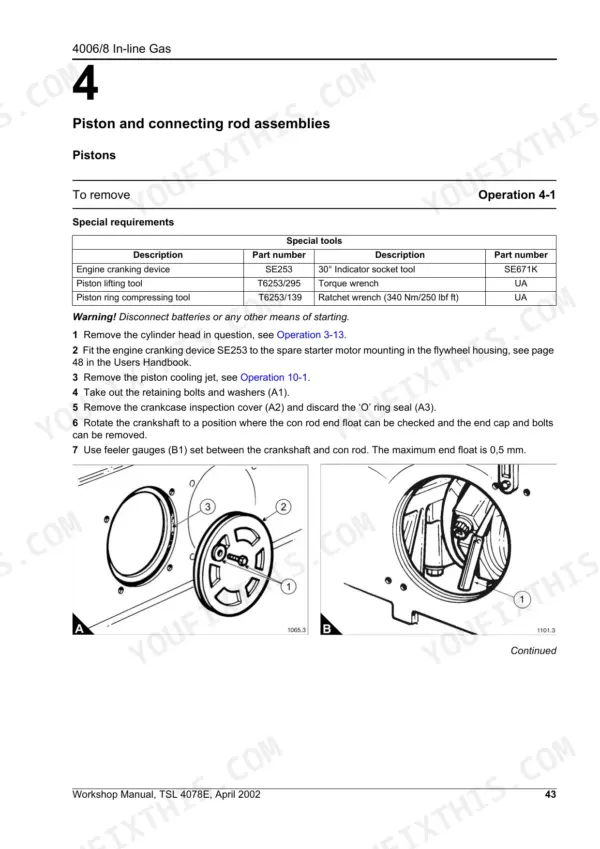
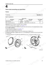
| Piston and Connecting Rod Assemblies | 43-52 | Pistons, To Remove, To Fit, Pistons and Rings, To Remove and to Fit, Piston Ring Identification, To Check, Con Rod |
| Crankshaft Assembly | 53-60 | Gearcase, Crankshaft Oil Seal, To Replace, Flywheel Housing Crankshaft Oil Seal, Crankshaft Damper 6 Cylinder Engines - Tuning Disc and Fan Drive Pulley, To Remove, To Fit |
| Gearcase and Timing Gears | 61-66 | Gearcase, To Remove and to Fit, Timing Gears, To Inspect, To Replace the Idler Gear Bush, To Align, Crankshaft Gear |
| Crankcase, Crankshaft and Cylinder Liners | 67-80 | Crankcase, To Invert, Crankshaft, To Remove Main Bearing Caps, Cylinder Engines, To Remove Main Bearing Caps and Tie Bars |
| Camshaft and Cam Followers | 81-88 | Camshaft End Float, To Check and to Set, Cam Followers and Housing, To Remove the Cam Follower Housing, To Inspect Cam Followers and Re-Fit the Housing, Camshaft, To Remove, To Fit |
| Aspiration System | 89-96 | Turbocharger, To Remove, To Fit, Charge Air Cooler, To Clean/Replace Charge Cooler Heat Exchanger Matrix |
| Lubricating System | 97-112 | Piston Cooling Jets, To Remove, To Fit, Oil Cooler, To Remove and to Fit, To Clean/Replace Oil Cooler Tubestack, To Pressure Test the Oil Cooler Assembly, Oil Pump |
| Gas System | 113-124 | Components of the Gas System, Gas Control Valve, To Maintain, Gas Mixer, To Clean the Venturi, Governor, Magnetic Pick-Up, To Clean and Set |
| Cooling System | 125-140 | Radiator, To Maintain, To Remove and to Fit, Chp System, Thermostats, To Check, Engine Coolant Pump, Engine Coolant Pump Shaft Support Bearing and Seal |
| Flywheel and Housing | 141-146 | Flywheel, To Remove, To Fit, Starter Ring Gear, To Replace, Flywheel Housing, To Remove and to Fit |
| Electrical System | 147-162 | Cylinder Engine Layout, Magnetic Sensor, To Clean and Set, Ignition Timing, To Set, To Troubleshoot, Volt Starter Motor, To Remove and to Fit |
| Auxiliary Equipment | 163-164 | Detonation Sensor Wiring Rail, Ren Valve Lubricating Oil Top Up System, Engine Cooling Radiator, Engine Coolant Pump, Raw Coolant Pump, Battery Charging Alternator |
| Special Tools | 165-166 | Tools for the Removal of Valve Gear, Air and Exhaust Manifolds, Water Pipes and Cylinder Heads, Tools for Intermediate Engine Overhaul |
Quick Reference Specifications
| Specification | Value | Page |
|---|---|---|
| All Models | ||
| Connecting rod bolts torque | 110 Nm (82 lbf ft) | p. 46 |
| Front oil seal insertion kit (6 cylinder) Part number | T6253/141 | p. 53 |
| Bore | 160 mm | p. 9 |
| Stroke | 190 mm | p. 9 |
| Valve clearances (engine cold) | 0.40 mm | p. 9 |
| 4006TESI LC, 4006TESI HC, 4006TESI 90 HC, 4006TESI 140 LC, 4006TESI 140 HC | ||
| Cubic Capacity (4006, 6-cylinder) | 22.921 litres | p. 9 |
| 4008TESI LC, 4008TESI HC, 4008TESI 90 HC, 4008TESI 140 LC, 4008TESI 140 HC | ||
| Cubic Capacity (4008, 8-cylinder) | 30.561 litres | p. 9 |
| 4006TESI LC, 4008TESI LC | ||
| Compression ratio (LC models) | 9.5:1 | p. 9 |
| 4006TESI HC, 4008TESI HC | ||
| Compression ratio (HC models) | 11.5:1 | p. 9 |
Perkins 4006, 4008 (4000 Series) Common Problems This Manual Covers
Perkins 4006/4008 gas engine overspeeds past 1800 rev/min during load changes, governor won't stabilize
Check the Gas System section starting page 113 for governor components and magnetic pick-up wiring. Confirm engine speed does not exceed the 1500/1800 rev/min overspeed limit during load changes. Inspect linkage for binding and verify gas control valve settings before adjusting the governor further.
Manual Section: Gas System p. 113Engine cranks slowly but won't start, or misfires intermittently under load
Check the DISN unit power, pick-up, and application indicators using the troubleshooting procedure on page 152. Verify each spark plug is torqued to 50 Nm and inspect for fouling or gap wear. Confirm the magnetic pick-up sensor clearance is correct before condemning the ignition module. Never use ether starter fluid; it is flammable and poisonous.
Manual Section: Electrical System p. 152Oil is contaminated with metal particles and cylinder walls show excessive wear after teardown
Check valve recession against the limit noted in the cylinder head assembly overview on page 15; if recession is excessive or the engine needs a major overhaul, fit a service exchange cylinder head. Torque connecting rod bolts to 110 Nm (82 lbf ft) per page 46, and replace worn O-ring seals with fluorosilicone material.
Manual Section: Piston and Connecting Rod Assemblies p. 46Oil leaking from the crankshaft seal area and wetting the flywheel housing after seal replacement
Replace the front oil seal with insertion kit T6253/141 (6 cylinder) or T6253/141A (8 cylinder), and the rear seal with kit T6253/140, per the crankshaft assembly section starting page 53. Clean the seal bore and journal before fitting, then torque main bearing bolts to 783 Nm as listed on page 10 before restarting.
Manual Section: Crankshaft Assembly p. 53Low oil pressure warning appears with metal particles found in the filter during routine service
Check the lubricating system section starting page 97 for oil pump and piston cooling jet procedures. Remove the oil pump to inspect for worn shaft bearings or scored gears, and pressure test the oil cooler assembly. While the engine is open, verify valve clearances at 0.40 mm per page 9 and top up oil per the maintenance schedule on page 5.
Manual Section: Lubricating System p. 97Frequently Asked Questions
What are the recommended service intervals?
The manual specifies maintenance intervals for certain components. For instance, the gas control valve should be cleaned and lubricated every 12 months for natural gas engines and every 6 months for biogas or landfill gas engines. Additionally, the zero pressure regulator should be stripped and checked at 24,000 hours by specialist personnel. p. 115
What fluids and capacities does this machine require?
The manual mentions various fluids used in the engine, such as engine oil, coolant, and silicone fluid for the crankshaft damper. However, specific capacities for these fluids (e.g., oil sump capacity, coolant system capacity) are not provided in the document. The gas system requires a minimum gas supply pressure of 15 mbar (1.5 kPa). p. 113
How to troubleshoot engine won't start?
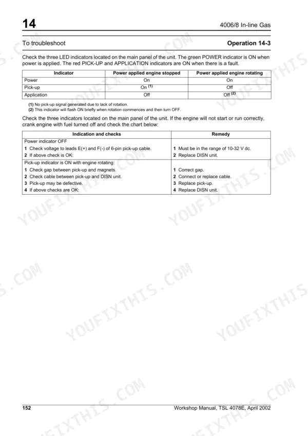
If the engine does not open on start-up, potential issues include no signal from the magnetic pick-up, excessive magnetic pick-up gap (0.5 - 0.8 mm), wiring faults, or a disconnected/incorrect speed setting potentiometer. The manual also provides a troubleshooting table for LED indicators on the DISN unit, suggesting checks for voltage (10-32 V dc) and replacing the DISN unit if necessary. p. 152
What are the valve clearance specifications?
The valve clearance specifications for both exhaust and inlet valves, when the engine is cold, are 0.40 mm (0.016”). p. 9
What torque specifications are listed?
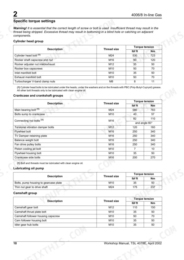
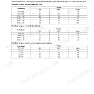
The manual provides extensive torque specifications for various engine components. For example, cylinder head bolts should be torqued to 723 Nm (530 lbf ft), main bearing bolts to 783 Nm (580 lbf ft), and connecting rod bolts to 110 Nm (82 lbf ft) plus an additional 60° angle. General torque settings for M8 bolts are 28 Nm (21 lbf ft) and for M10 bolts are 56 Nm (41 lbf ft). p. 10
How will I receive this Perkins 4006/8 In-line Gas & variants Workshop Manual?
Immediate download of the complete 166-page searchable Workshop Manual. Access it on any device, from a laptop at your desk to a phone in the field.
Is this Perkins 4006/8 In-line Gas & variants Workshop Manual printable?
Yes. Print the sections you need to take out to the shop for your own use. Standard letter or A4 paper works.
Reviews
There are no reviews yet.