
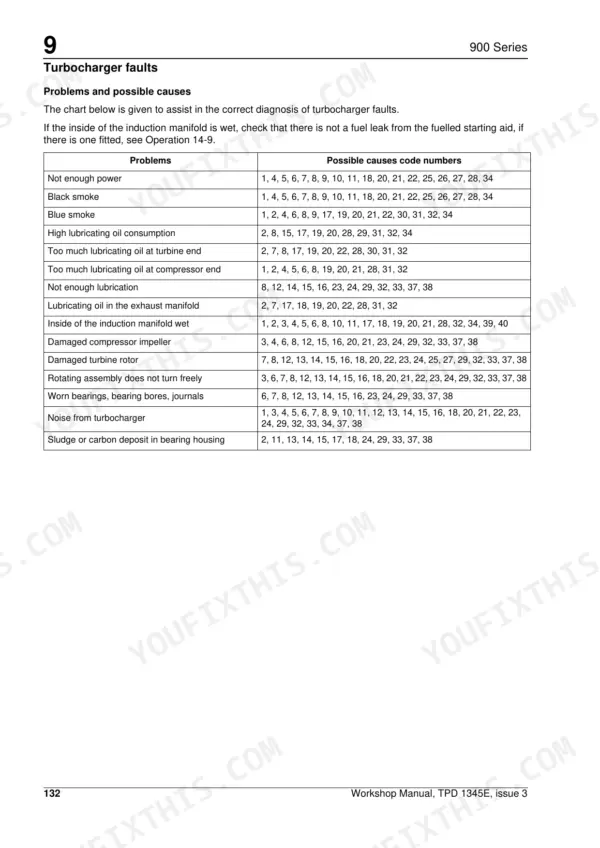
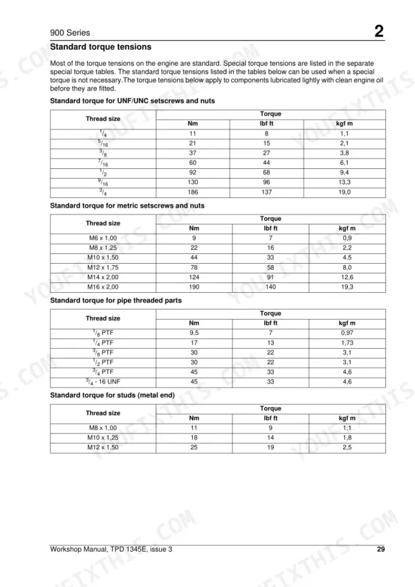
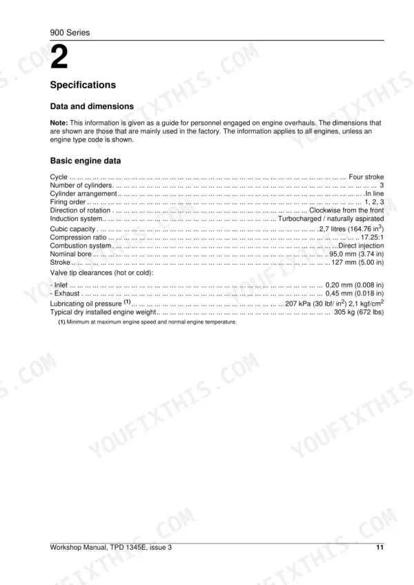
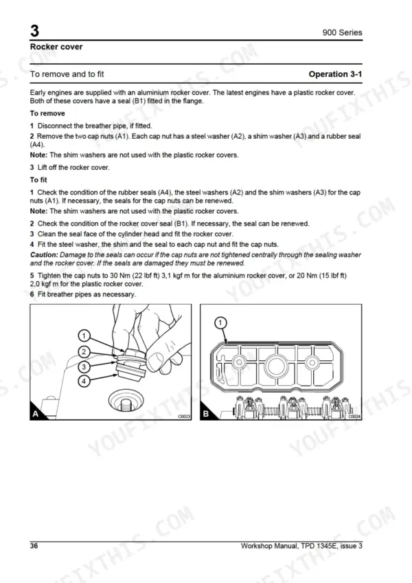
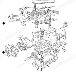
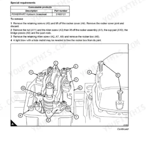
Rebuilding a Perkins 900 Series diesel? This 240-page Perkins 900 CP and CR shop manual PDF (factory publication TPD 1345) takes you from cylinder head and valve work through crankshaft, timing case, cylinder liners, and complete engine timing. You get full data and dimensions, standard and special torque tensions, compression test data, and step-by-step procedures for the Delphi fuel injection pumps, atomisers, and turbocharger. Turbocharger fault tables and alternator diagnosis are in here too, plus the special tools section: valve guide tools, timing pins, crankshaft seal drivers, piston height gauge. Set atomiser nozzle protrusion between 1.6 and 2.13 mm on KB-code injectors, and pull the fuel pump gear setscrews to 27 Nm (20 lbf ft). Guesswork wrecks liners. Bookmarked and keyword-searchable; download it, walk to the engine, and find your spec in seconds.
What's Inside This Perkins 900 Series (CP, CR) Manual
| System | Pages | Key Topics |
|---|---|---|
| General Information | 1-20 | Introduction, Engine Views, Engine Identification, Safety Precautions, Engine Lift Equipment, Viton Seals, Powerpart Recommended Consumable Products |
| Specifications | 21-44 | Data and Dimensions, Thread Sealant, Standard Torque Tensions, Special Torque Tensions, Compression Test Data |
| Cylinder Head Assembly | 45-72 | Rocker Assembly, Valves and Valve Springs |
| Piston and Connecting Rod Assembly | 73-86 | Big End Bearing, Piston Rings |
| Crankshaft Assembly | 87-100 | Crankshaft Pulley, Rear Oil Seal Assembly, Thrust Washers, Main Bearings, Crankshaft |
| Timing Case and Drive Assembly | 101-120 | Timing Case Cover, Front Oil Seal, Idler Gear and Hub, Fuel Pump Gear, Camshaft Gear, Crankshaft Gear, Timing Case, Camshaft |
| Cylinder Block Assembly | 121-130 | Cylinder Block, Cylinder Liner |
| Engine Timing | 131-136 | Top Dead Centre, Valve Timing, Fuel Injection Pump Timing, Locking Angle |
| Aspiration System | 137-148 | Turbocharger, Turbocharger Faults, Closed Breather System, Open Breather System, Breather Separator |
| Lubrication System | 149-172 | Lubrication System Flow Diagram, Filter Canister, Filter Head, Canister Type Lubricating Oil Cooler, Sump, Oil Strainer and Suction Pipe Assembly, Lubricating Oil Pump |
| Fuel System | 173-204 | Fuel Filter, Atomisers, Fuel Lift Pump, Delphi Fuel Injection Pumps |
| Cooling System | 205-216 | Cooling System Flow Diagram, Thermostat, How to Fill the Cooling System, Coolant Pump, Fan |
| Flywheel and Flywheel Housing | 217-220 | Flywheel, Ring Gear, Flywheel Housing |
| Electrical Equipment | 221-234 | Alternators, Starter Motors |
| Auxiliary Equipment | 235-236 | Section Not Used |
| Special Tools | 237-240 | Valve Guide Tools, Piston Height Gauge, Crankshaft Seal Tools, Fuel Pump Gear Puller, Valve Spring Compressor, Timing Pins |
Quick Reference Specifications
| Specification | Value | Page |
|---|---|---|
| Maximum protrusion of the atomiser nozzle (Code letter KB) | 1,6/2,13 mm (0.0629/0.0838 in) | p. 22 |
| Maximum protrusion of the atomiser nozzle (Code letter KK) | 3,49/4,01 mm (0.1374/0.1579 in) | p. 22 |
| Static pressure - no delivery | 41/69 kPa (6/10 lbf/in2) 0,4/0,7 kgf/cm2 | p. 36 |
| Test pressure at 1000 rev/ min | 42/70 kPa (6/10 lbf/in2) 0,4/0,7 kgf/cm2 | p. 36 |
| Setscrews for the gear of the fuel injection pump torque | 27 Nm (20 lbf ft) 2,7 kgf m | p. 41 |
| Torx screw, for the gear of the fuel injection pump torque | 27 Nm (20 lbf ft) 2,7 kgf m | p. 41 |
| Cubic capacity | 2,7 litres | p. 21 |
| Inlet valve tip clearance | 0,20 mm | p. 21 |
| Exhaust valve tip clearance | 0,45 mm | p. 21 |
| Lubricating oil pressure | 207 kPa | p. 21 |
| Cylinder head setscrew torque (initial) | 70 Nm | p. 60 |
| Thermostat 'Starts to open' temperature | 80/84 °C | p. 36 |
Perkins 900 Series (CP, CR) Common Problems This Manual Covers
Perkins 900 series CP or CR cranks strong but will not start, fires intermittently then dies
Check fuel level and bleed air from the system at the filter and injection pump. Test the lift pump next: static pressure with no delivery should read 41/69 kPa (6/10 lbf/in2), listed on page 36. Work through the fuel system procedures starting on page 173, and torque the lift pump setscrews to 22 Nm on reassembly.
Manual Section: Fuel System p. 173Black smoke under load with power loss, turbocharger whines at full throttle
Remove and inspect the air filter element before blaming the turbocharger. Check the rotor for carbon deposits and shaft play, then run the fault checks on page 142. Test the atomisers next; KB code nozzles must open at 300 atm (30,4 MPa), listed with the atomiser service settings on page 36, so pull any suspect unit and bench test it before condemning the turbo.
Manual Section: Aspiration System p. 142Low oil pressure warning at idle after oil change, gauge drops further when hot
Verify the reading with a mechanical gauge before tearing anything down; the lubricating oil pressure spec is 207 kPa, listed on page 21. Drain the sump and inspect the oil strainer and suction pipe for blockage using the lubrication system procedures starting on page 149. If pressure stays low with a clean strainer, check main bearing clearances.
Manual Section: Lubrication System p. 149Losing coolant with white smoke on startup, temperature gauge climbs under load
Test the thermostat in heated water; it must start to open at 80/84 degrees C (176/183 F), per page 36. Check the coolant pump drain hole for intermittent leakage and inspect belt tension, following the cooling system procedures on page 205. If coolant keeps vanishing with white exhaust smoke, pressure test the system for a head gasket leak.
Manual Section: Cooling System p. 205Loud knocking under load and constant ticking from the valve cover at idle speed
Adjust the valve tip clearances first: 0,20 mm inlet and 0,45 mm exhaust, from the specs on page 21. If the knock continues under load, run a compression test on each cylinder and listen at the block with a stethoscope; worn big end or main bearings need the crankshaft procedures starting on page 87.
Manual Section: Cylinder Head Assembly p. 45Frequently Asked Questions
How do I bleed air from the fuel system on a Perkins 900 Series CP/CR engine?
To bleed the fuel system, loosen the vent plug on the pre-filter head and operate the fuel lift pump priming lever until fuel free of air flows out. Then, loosen the banjo bolt on the top of the main filter head and repeat the priming process until air-free fuel flows. Finally, loosen the high-pressure connections at two atomisers and operate the starter motor until fuel flows, then tighten the connections. p. 197
What are the torque specifications for the cylinder head, rocker cover, and water pump?
Cylinder head setscrews (positions 1-8) are tightened to 70 Nm (52 lbf ft) plus two additional 60-degree turns. Rocker cover cap nuts are 30 Nm (22 lbf ft) for metal covers or 20 Nm (15 lbf ft) for plastic covers. The coolant pump setscrews are tightened to 44 Nm (33 lbf ft), given with the coolant pump procedure on page 211. p. 60
How do I set the injection pump timing on a Perkins 900 Series engine?
For pin-timed pumps, set the engine to TDC on the compression stroke for number 1 cylinder. Insert the timing pin (Part number 27610033) through the fuel pump gear and hub into the recess in the pump body. If the pin can be fully inserted without resistance, the timing is correct. p. 136
What is the correct valve tip clearance for the Perkins 900 Series engine?
The valve tip clearance for the inlet valves is 0,20 mm (0.008 in) and for the exhaust valves is 0,45 mm (0.018 in). These clearances apply whether the engine is hot or cold. p. 21
What is the recommended service interval for the lubricating oil cooler?
The recommended service interval for the canister type lubricating oil cooler is 2000 hours of operation. p. 153
What do I get after purchasing this Perkins 900 manual?
You download the Shop Manual yourself: 240 pages, searchable PDF, available immediately. Keep a copy on every device you use.
Is printing allowed for this Perkins 900 Shop Manual?
Yes. Many mechanics print the section they need for their own shop and bring it to the bench.


Reviews
There are no reviews yet.