
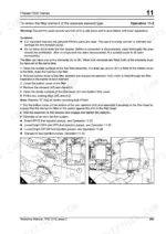
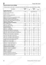
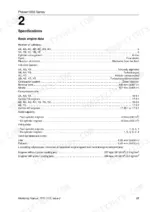
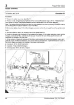
Need factory data for your Perkins Phaser or 1000 Series diesel engine? This 440-page workshop manual PDF (OEM #TPD 1312E) is the official Perkins repair manual for both engine families, cylinder head to flywheel housing. You get engine wiring diagrams, compression test data, and step-by-step rebuild procedures for every major assembly: pistons, crankshaft, timing case, turbocharger, plus the complete fuel system covering Bosch, Lucas/Delphi, and Stanadyne injection pumps. A full torque settings section lists factory figures for every fastener. Set inlet valve tip clearance at 0.20 mm cold, exhaust at 0.45 mm, and torque the sump drain plug to 34 Nm before you refill. No more chasing specs across forum threads while your engine sits in pieces. The bookmarked PDF opens on any device; pull it up on a tablet next to the block and start wrenching.
What's Inside This Perkins Phaser Manual
| System | Pages | Key Topics |
|---|---|---|
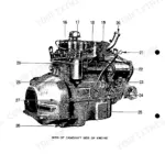
| General Information | 15-24 | Introduction, Engine Views, Engine Identification, Safety Precautions, Asbestos Joints, Viton Seals, Engine Lift Equipment, Powerpart Consumable Products |
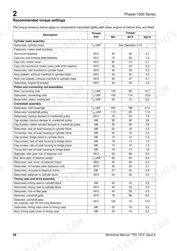
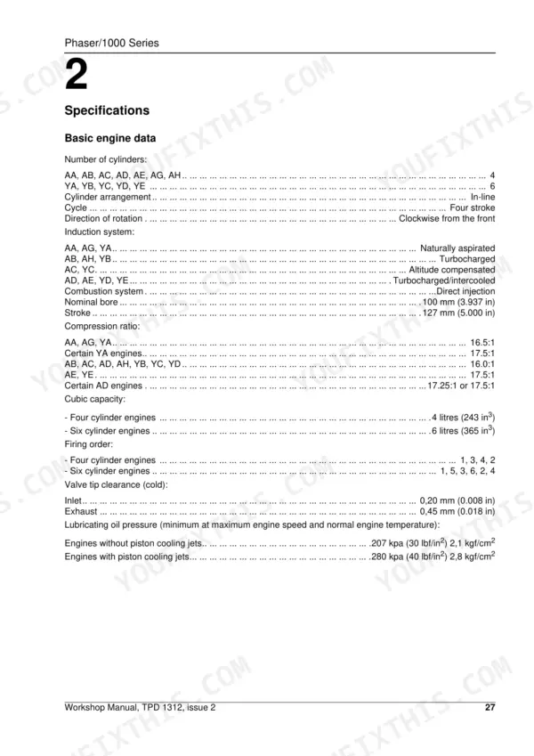
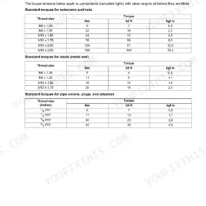
| Specifications | 25-60 | Data and Dimensions, Thread Sealant, Recommended Torque Settings, Compression Test Data |
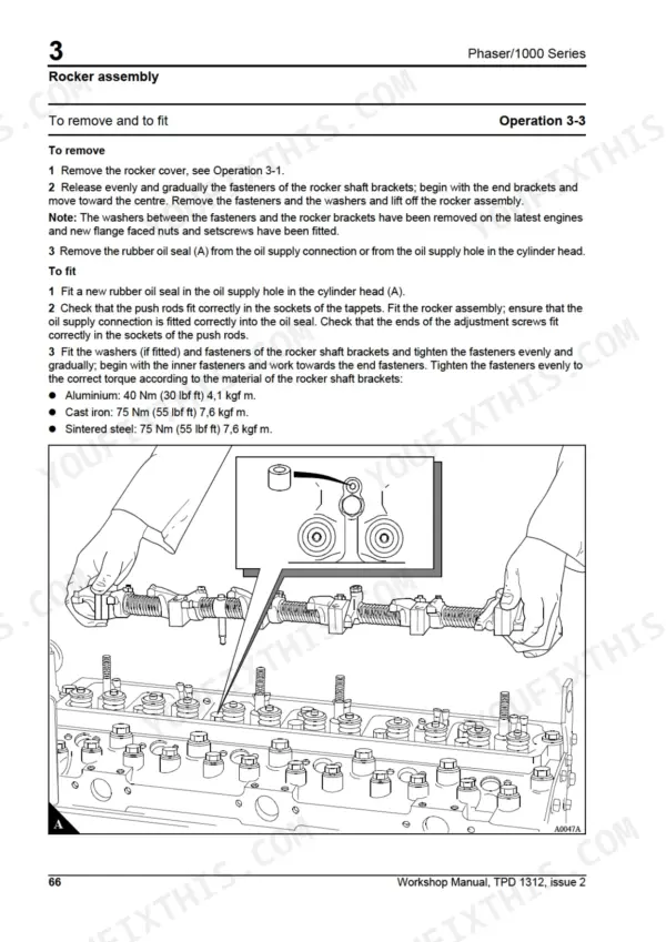
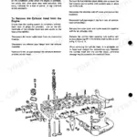
| Cylinder Head Assembly | 61-84 | Rocker Cover, Rocker Assembly, Valve Tip Clearances |
| Piston and Connecting Rod Assemblies | 85-100 | Big End Bearing, Piston and Connecting Rod, Piston Rings, Piston and Connecting Rod Assembly, Piston and Piston Rings, Connecting Rod, Small End Bush, Piston Cooling Jets |
| Crankshaft Assembly | 101-142 | Crankshaft Pulley, Crankshaft Pulley and Damper, Rear Oil Seal Assembly, Thrust Washers, Main Bearings, Crankshaft, Balancer Unit |
| Timing Case and Drive Assembly | 143-166 | Timing Case Cover, Front Oil Seal, Idler Gear and Hub, Idler Gear and Hub for the Bendix or Knorr-Bremse Compressor, Fuel Pump Gear, Camshaft Gear, Crankshaft Gear, Timing Case |
| Cylinder Block Assembly | 167-184 | Cylinder Block, Cylinder Liner |
| Engine Timing | 185-214 | Standard Operations, Engines Fitted with Bosch Epve Fuel Injection Pumps, Engines Fitted with Bosch Mw In-Line Fuel Injection Pumps |
| Aspiration System | 215-234 | Turbocharger, Turbocharger Faults, Open Engine Breather, Closed Breather System |
| Lubrication System | 235-256 | Lubrication System Flow Diagram, Lubrication System Flow Diagram for the Relief Valve and Balancer, Filter Canister, Filter Head, Sump, Oil Strainer and Suction Pipe |
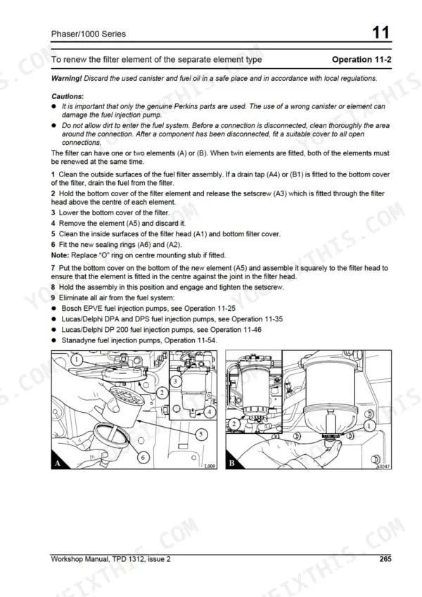
| Fuel System | 257-340 | Cold Start Advance Unit, Fuel Filter Elements, Fuel Filter Canister, Atomisers, Fuel Lift Pump, Bosch Epve Fuel Injection Pump, Lucas/Delphi Dpa and DPS Fuel Injection Pumps |
| Cooling System | 341-384 | Thermostats, Coolant Pump, Fan, Fan Drive, Lubricating Oil Cooler, Cooler By-Pass Valve, Intercooler |
| Flywheel and Housing | 385-390 | Flywheel, Ring Gear, Flywheel Housing |
| Electrical Equipment | 391-404 | Alternators, Starter Motors, Starting Aid |
| Auxiliary Equipment | 405-432 | Wabco Compressors, Compressor Drive for Wabco Compressors, Bendix Compressors, Knorr-Bremse Compressors, Power Steering Pump |
| Special Tools | 433-440 | List of Special Tools |
Quick Reference Specifications
| Specification | Value | Page |
|---|---|---|
| Inlet valve tip clearance (cold) | 0,20 mm (0.008 in) | p. 25 |
| Exhaust valve tip clearance (cold) | 0,45 mm (0.018 in) | p. 25 |
| sump fasteners | 22 Nm (16 lbf ft) | p. 243 |
| sump drain plug | 34 Nm (25 lbf ft) | p. 243 |
| Nominal Bore | 100 mm | p. 25 |
| Stroke | 127 mm | p. 25 |
| Lubricating Oil Pressure (without piston cooling jets) | 207 kPa | p. 25 |
| Lubricating Oil Pressure (with piston cooling jets) | 280 kPa | p. 25 |
| Cylinder Head Setscrew Torque | 110 Nm | p. 73 |
| Starting Aid Fuel Flow Rate | 3,5/5,9 ml/min | p. 53 |
| Starter Cable Resistance (12V) | 0.0017 ohms | p. 53 |
Perkins Phaser Common Problems This Manual Covers
Perkins Phaser 1000 Series losing power under load with black exhaust smoke and turbocharger whine
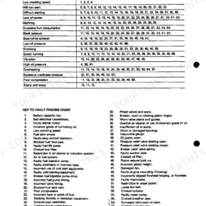
Check the air filter and intake hoses for restriction first. Inspect the turbocharger shaft for excessive play and oil in the compressor housing; removal and inspection procedures start in the Aspiration System section on page 215. Verify lubricating oil pressure holds 207 kPa on engines without piston cooling jets, 280 kPa with jets (page 25); low pressure ruins turbo bearings fast.
Manual Section: Aspiration System p. 215Low oil pressure warning at idle after oil change, gauge drops once engine warms up
Drain the sump and inspect the oil strainer and suction pipe for sludge blockage; procedures are in the Lubrication System section starting on page 235. Refit the drain plug with a new O ring and torque it to 34 Nm (page 243). Verify pressure hot: 207 kPa without piston cooling jets, 280 kPa with jets.
Manual Section: Lubrication System p. 235Engine turns over slowly in cold weather and will not fire, starting aid seems ineffective
Test battery condition and total starter cable resistance; a 12 volt circuit must not exceed 0.0017 ohms (page 53). Check starter engagement and connections per the Electrical Equipment section starting on page 391. Measure starting aid fuel flow, which should read 3,5/5,9 ml/min depending on type, and replace the aid if flow is low.
Manual Section: Electrical Equipment p. 391Loud tapping noise from rocker cover at idle, engine misfires under light load
Remove the rocker cover and measure valve tip clearances with the engine cold: 0,20 mm inlet, 0,45 mm exhaust (page 25). Adjust at the rocker adjusting screws and recheck each cylinder. Inspect the rocker assembly and pushrods for wear using the Cylinder Head Assembly procedures starting on page 61. Recurring tight clearances point to valve seat recession.
Manual Section: Cylinder Head Assembly p. 61Frequently Asked Questions
What are the torque specifications for the cylinder head bolts on the Perkins Phaser 1000 Series?
The manual does not give a single torque figure for the cylinder head setscrews. Its recommended-torque table lists 'Setscrews, cylinder head, 1/2 UNF' as 'See Operation 3-10', because they are tightened in stages rather than to one value. Operation 3-10, To fit, on printed page 75 carries that sequence; Operation 3-9 on page 73 is the removal procedure. Work through the staged sequence in Operation 3-10 rather than any single figure. p. 75
What is the correct valve tip clearance for the Perkins Phaser 1000 Series engines?
The valve tip clearance for cold engines is 0,20 mm (0.008 in) for the inlet valves and 0,45 mm (0.018 in) for the exhaust valves. p. 25
What is the torque specification for the connecting rod nuts?
The nuts for the connecting rods must be tightened to 125 Nm (92 lbf ft) 12,7 kgf m. p. 56
What is the minimum lubricating oil pressure for engines with piston cooling jets?
For engines equipped with piston cooling jets, the minimum lubricating oil pressure at maximum engine speed and normal operating temperature is 280 kPa (40 lbf/in²) 2,8 kgf/cm². p. 25
What is the correct belt deflection for the alternator drive belts?
With moderate thumb pressure of 45 N (10 lbf) 4,5 kgf applied at the centre of the longest free length, the correct belt deflection is 10 mm (3/8 in). p. 394
Do I get instant access to this Perkins Phaser Repair Manual?
You get a 440-page scanned PDF that downloads instantly after checkout. Open it on your laptop, tablet, or phone, and bring it right to the shop floor.
Can I print specific sections of this Perkins Phaser Repair Manual?
No restrictions at all. Print individual pages, full chapters, or the entire manual. The PDF is completely unlocked.


Reviews
There are no reviews yet.